- Semiconductor BusinessHOME
- Products and Services of Macnica,Inc.
-
technical information

-
Events and Seminars
- Handling Manufacturer
- Support
- Inquiry
- Click here to purchase products
- Semiconductor business e-mail magazine registration
![]()
![]() Narrow down by specifying conditions
Narrow down by specifying conditions
現在2182件がヒットしています。check

When it comes to Analog Devices design tools, many people think of LTspice. It's free and very useful!
Besides LTspice, did you know there is another very useful tool for designing DC/DC converters?
This time, I will introduce this convenient free design tool LTpowerCAD.
Install LTpowerCAD
Download the installer from the Analog Devices LTpowerCAD page.
For the page, please visit Analog Devices' "LTpowerCAD/LTpowerPlanner" page.
Click on the Download LTpowerCAD button to download the zip file (LTpowerCADII.zip). Click on setup.exe in the unzipped ZIP file to install.
After installation, in order to update to the latest version, click OK when asked "Do you want to Sync/Release?"
If you are not asked, click on the LTpowerCAD icon on your desktop to run it.
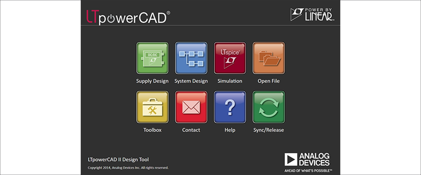
This will open the menu screen shown in Figure 1. Click "Sync/Release" in the bottom right of the menu to perform the version upgrade.
Enter the power supply specifications and select a device
Clicking on "Supply Design" from the menu screen in Figure 1 will open a menu screen in Figure 2 where you can enter device specifications and search for parts.
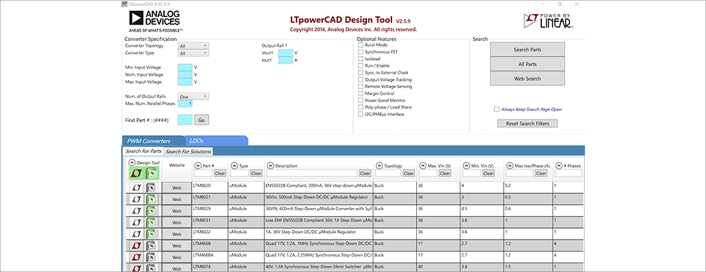
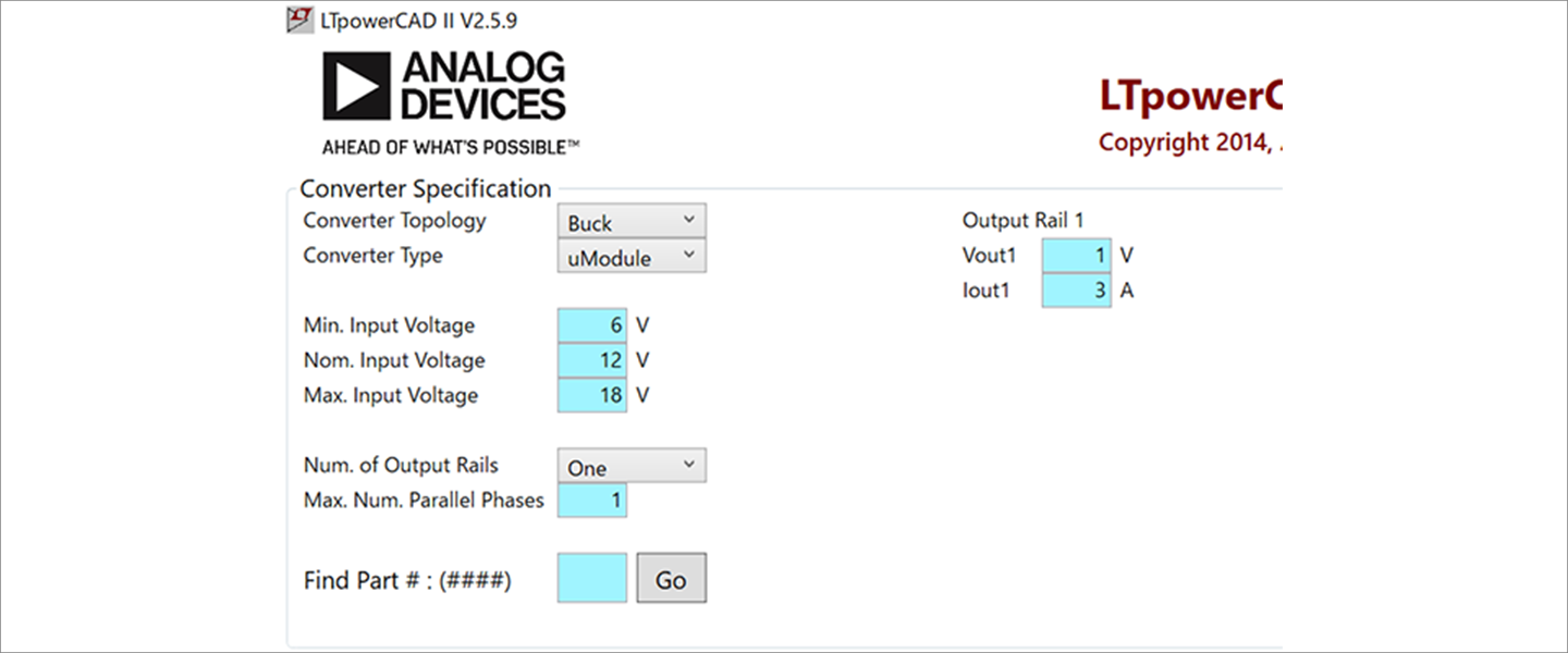
Enter the power supply specification in the Converter Specification in the upper left part of Figure 2.
The power supply specifications are a step-down (Buck) μModule with an input voltage range of 6 to 18 V (Typ. 12 V) and a single output of 1.0 V/3 A (Figure 3).
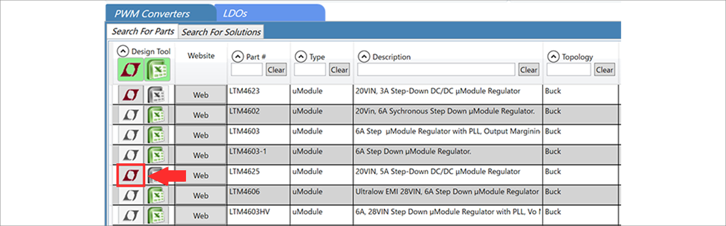
After entering the specifications, click the "Search Parts" button in the upper right corner and a table of part numbers will appear in the "Search for Parts" section of the tool (Figure 4).
Clicking on the active LTM4625 icon highlighted in red will open the design project file (Figure 5).
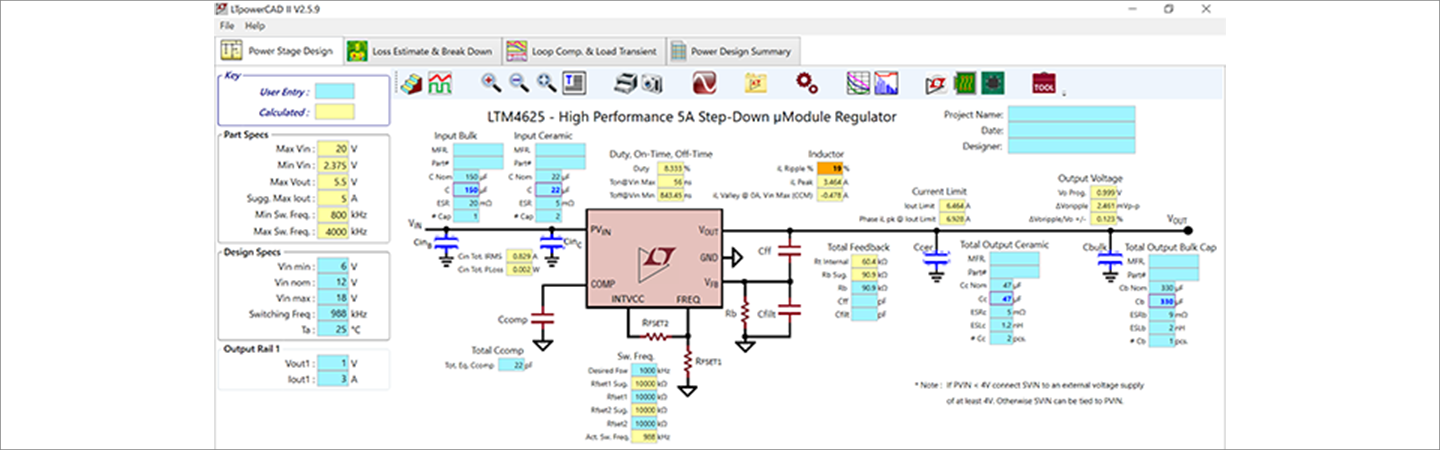
Check project file
The yellow cells in this table represent the device specifications (Parts Specs), and the light blue cells are input cells for designers.
If all the yellow cells are yellow, then you are within the device specifications and can use this schematic as is in your design. If there are any issues, they will turn red or orange.
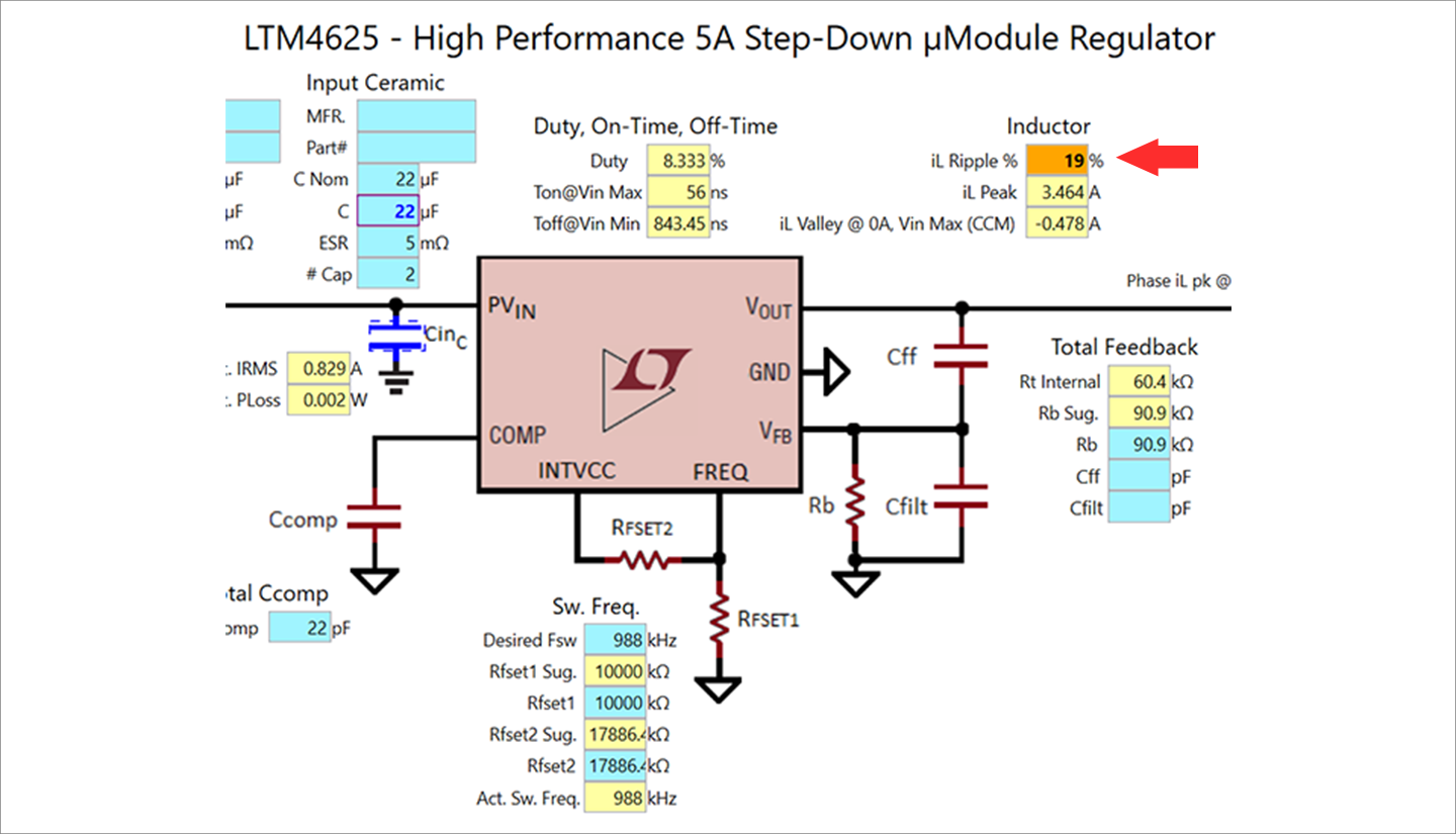
This time, the inductor iL Ripple is orange, so a specification change is required (red arrow in Figure 6).
Module products have a built-in inductor and the inductance value cannot be changed, so we take countermeasures by changing the switching frequency.
On the left side of the sheet, change the Switching Freq. under Design Specs from 988KHz to 900KHz. This will bring it down to 20%, which is within the specification range and shows as a yellow cell, and the design is complete (Figure 7).
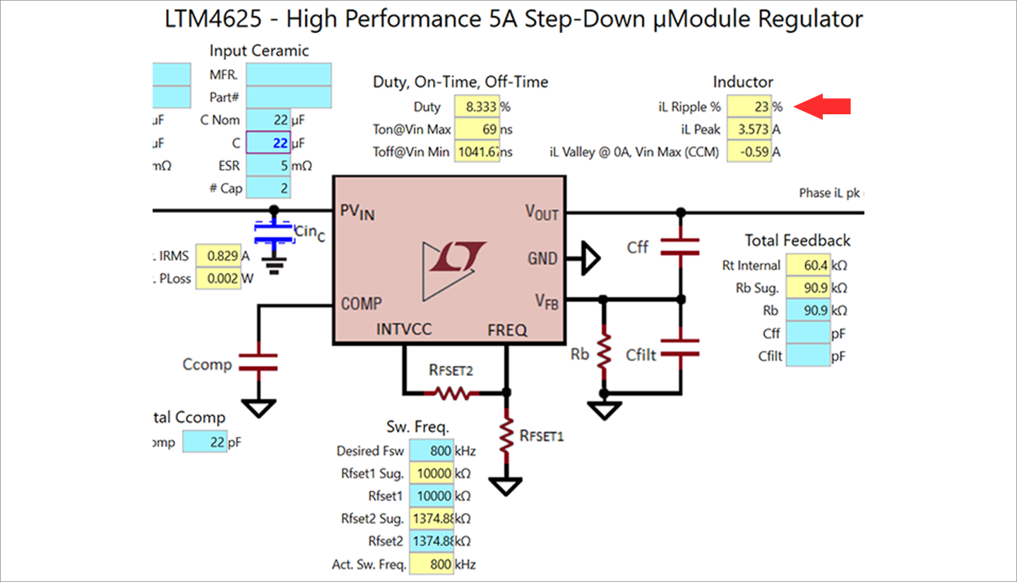
You can save the project file you designed.
It is convenient to select Save AS from the File menu and save it with a name of your choice.
At the end
In this way, LTpowerCAD is a tool that makes it easy to select devices that meet the power supply specifications and design the circuit.
It is very convenient because it automatically calculates the constants of the surrounding inductors and capacitors on the desk.
If you haven't used LTpowerCAD yet, please download LTpowerCAD from the link below!
Please use it for power supply design.
Download LTpowerCAD here
Click here for recommended articles/materials
Click here for recommended seminars/workshops
Inquiry
If you have any questions regarding this article, please contact us below.
Analog Devices Manufacturer Information Top
To return to the Analog Devices manufacturer information top page, please click below.