- 半導体事業HOME
- マクニカの製品・サービス
-
技術情報

-
イベント・セミナー
- 取扱メーカー
- サポート
- お問い合わせ
- 製品購入はこちら
- 半導体事業のメルマガ登録
![]()
![]() 条件を指定して絞り込む
条件を指定して絞り込む
現在2183件がヒットしています。check
車載アプリケーションにおいて、DC/DCコンバーターのレイアウトは非常に重要です。データシートの参照回路図通りに設計をおこなったとしても、デバイスが動作しなかったり、ノイズが多くなってしまったりすることがあります。それらの事象に気づくタイミングは残念ながらすでに基板を作ったあとになり、修正にかけられる時間はあまりないケースが多いです。これらの問題の多くは、作成した基板のレイアウトに起因することが多いです。
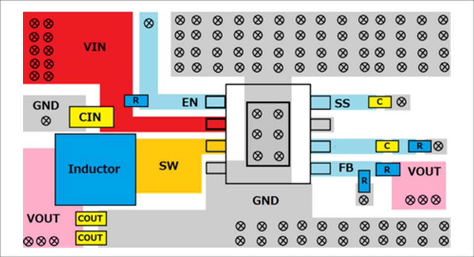
例えば、図1のDC/DCコンバーターのレイアウトですが、問題が無いように見えますが量産していくと、問題が発生する可能性があるので注意が必要です。
設計を始める前にデモボードによる検証がおすすめ
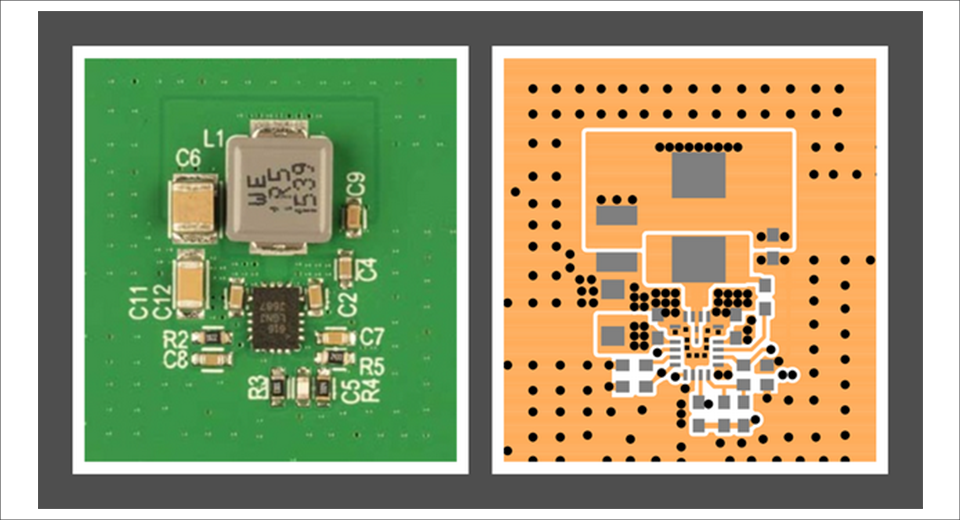
DC/DCコンバーターを使うときには、まず一番最初はデモボード等での実験をお勧めします。その結果、正常な波形が得られ、またデモボードのレイアウト情報を参考に実際にアプリケーション用の基板をつくることができます。デモボードのレイアウトをそのまま使用できれば良いですが、実際にはさまざま制約(面積、各社の基板ルールなど)により、理想的なレイアウトを実施するのが難しいケースが多いです。そのため、事前にDC/DCコンバーターの動作において、どういうレイアウトが重要になるか、「レイアウトのポイント」以降で説明いたします。
レイアウトで最も重要なホットループ
車のアプリケーションは、CISPRR25 Class5等のEMIの要求が来ることが多く、この点において一番レイアウトで重要な点はホット・ループといわれております。
ホットループについて説明します。HI Side側のFETがONでLow Side側のFETがOFFのときのオン・サイクルの間、AC電流は赤のループを流れます。Hi Side側のFETがOFFでLowside側のFETがONのときのオフ・サイクルの間、AC電流は青のループを流れます。どちらの電流も台形波になります。ゼロからIpeakに切り替わってゼロに戻るスイッチングAC電流は、緑のループのみに流れ、この緑のループがもっともAC電流およびEMIエネルギーが大きくなります。この緑のループをホットループと呼んでいます。

EMIを小さくするためには、緑色のループでの影響をできる限り小さくする必要があります。このループでの磁場強度は、スイッチング電流とループの面積に比例します。
そのため、ノイズを考慮したレイアウトを設計する最初のステップは、ホット・ループをできる限り小さく抑えることです。銅のスペーシングは、デザイン・ルールで許容される限り小さくする必要があります。
ホット・ループの一番近い場所には、最も短く平坦なセラミック・デカップリング・コンデンサーを使用します。ホット・ループにいくつかのブロッキング・コンデンサーやデカップリング・コンデンサーを並列に使用するのは問題ありません。
レイアウトのポイント
DC/DCコンバーターの設計では、ホットループに気を付けて設計してください。
よく車載アプリケーションで使われる、LT86xxシリーズのうちの一つ、LT8640を例にとって説明した「低ノイズ電源回路設計の3つのポイント」の記事も合わせてご参照ください。
おすすめセミナー/ワークショップはこちら
お問い合わせ
本記事では、車載アプリケーションにおいて、DC/DCコンバーター設計の勘所について紹介をさせていただきました。詳細を知りたいという方は以下からお問い合わせください。
アナログ・デバイセズ メーカー情報Topへ
アナログ・デバイセズ メーカー情報Topに戻りたい方は以下をクリックしてください。