- Semiconductor BusinessHOME
- Products and Services of Macnica,Inc.
-
technical information

-
Events and Seminars
- Handling Manufacturer
- Support
- Inquiry
- Click here to purchase products
- Semiconductor business e-mail magazine registration
![]()
![]() Narrow down by specifying conditions
Narrow down by specifying conditions
現在2158件がヒットしています。check
![[Introduction to accelerometer] Let's use the tap detection function](/business/semiconductor/articles/Article_140171_cover.png)
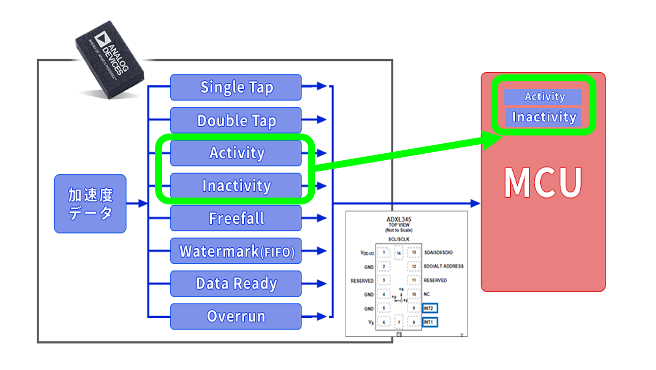
In the [Introduction to Accelerometer] series, we will explain the basic usage and application methods, focusing on analog devices' accelerometers. In this article, we will check the operation using the acceleration sensor "ADXL345" and "Arduino". The digital output type acceleration sensor "ADXL345" has built-in data processing and event interrupt functions. Therefore, it is possible to reduce the load on the host (microcomputer) side. This time, instead of using the "active/inactive detection function," which is one of the motion detection functions introduced previously, I would like to create a detection function on the Arduino program. Please refer to the previous article for details on the "active/inactive detection function".
[Introduction to accelerometer] Click here for the series list
Let's implement the motion detection function (activity detection)
This time, as shown in the figure below, we will implement the "active/inactive detection function", which is a digital operation function installed in the ADXL345, on the Arduino side. One of the reasons for doing this is that some accelerometers have analog outputs. Analog output type products do not have digital calculation functions such as "active/inactive detection function" built in the sensor side, so after AD conversion, the detection function must be performed on the host processor side such as a microcomputer. Therefore, this time, I would like to implement the data processing of the ADXL345's activity detection function on the Arduino side.
Things to prepare
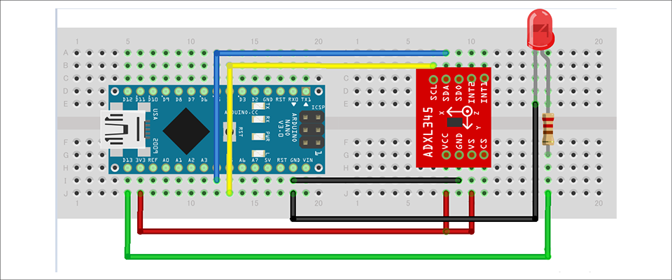
Here is what I prepared to evaluate the accelerometer this time.
・PC with Arduino IDE installed (Download Arduino IDE from here)
・ Arduino Nano compatible board
・Others (USB cable (for Arduino and PC connection), breadboard, wires)
Combine the above parts to form a circuit as shown in the figure below. Power supply to Arduino Nano is supplied by USB bus power from PC. The ADXL345 supports SPI and I2C interfaces, but this time we will use the I2C interface.
Also, since the interrupt pins INT1 and INT2 are not used, they do not need to be connected this time.
Program content
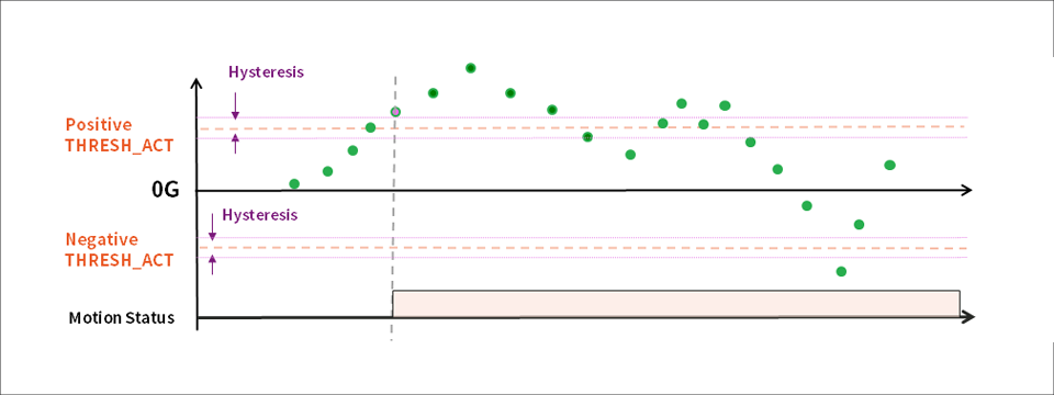
In the program, when "motion detection" exceeds the active threshold acceleration set in the program, the status is changed to active as shown in the figure and the LED is lit.
As a flow, X, Y, and Z acceleration data are acquired at a certain period of time and compared with the threshold acceleration. The flag is activated when the latest acquired data exceeds the threshold from the state where the previous acquired data does not exceed the threshold. In addition, as shown in the figure, a hysteresis is added to the threshold to suppress data fluctuations near the active threshold. This time, we simply set the motion status to active when any one of the X, Y, and Z axis acceleration exceeds an arbitrary threshold. Since the function to change the status is not included, the LED will remain lit when it becomes active status. You can download the project file created with the Arduino IDE, so if you are interested, please get it from the "Document Download" below.
operation check
Let's check the operation with the created program. From a still state, adding movement and gradually increasing the speed of movement, active detection was performed and the LED was lit.
This time, it is judged to be active when the acceleration threshold is exceeded, but there is no function to change the active status after that. So the LED stays lit after active status. Next time, I would like to add a program that, like the inactivity detection function installed in the ADXL345, turns off the LED when there is little change in acceleration for a certain period of time after detecting activity.
This time, I tried to incorporate the functions installed in the ADXL345 as data processing on the Arduino side. When implemented in software, the number of codes such as status variable management and conditional branching increases, so I was able to appreciate the built-in digital functions again.
Download the sample code verified this time
We provide the Arduino project file that we implemented this time. Please apply from here and give it a try.
About Accelerometer ADXL345
The ADXL345 used this time is a 3-axis digital output acceleration sensor. The main features are as follows.
・A standard accelerometer that is very easy to use with built-in ADC, operation function block, and FIFO
・Acceleration data adopts general I2C/SPI in digital serial method
・The 3-axis type sensor is a rectangular coordinate (X, Y, Z), and the acceleration acting on each axis can be obtained.
・The maximum detectable acceleration can be set in the range of 2g to 16g, and the sampling range is as wide as ~3.2kHz, so it can be applied to various applications such as impact, tilt, and motion detection.
・Flexible mode to reduce current consumption
For more information on the ADXL345, visit www.adxl345.com. data sheet Please refer to. Also, this accelerometer is very easy to use, so if you want to evaluate an accelerometer from now on, please try it on the evaluation board.
At the end
If you have any questions about the contents of this article, or if you have any problems with selecting or using accelerometers, please contact us from the following.
Analog Devices Manufacturer Information Top
If you want to return to Analog Devices Manufacturer Information Top, please click the button below.
![[Introduction to accelerometer] Thumbnail image of Let's use the interrupt function](/business/semiconductor/articles/9d56e574e3a24bcf3f076e91d90f4a53.png)