- Semiconductor BusinessHOME
- Products and Services of Macnica,Inc.
-
technical information

-
Events and Seminars
- Handling Manufacturer
- Support
- Inquiry
- Click here to purchase products
- Semiconductor business e-mail magazine registration


 Narrow down by specifying conditions
現在2207件がヒットしています。check

Introduction
Let's use LTspice - In the introductory section, we gave an overview of LTspice and introduced its simple functions.
In this article, I will explain how to start LTspice and the basic operation method while designing a simple circuit.
Let's use LTspice series list is here
Circuit design
I would like to start designing circuits with LTspice right away.
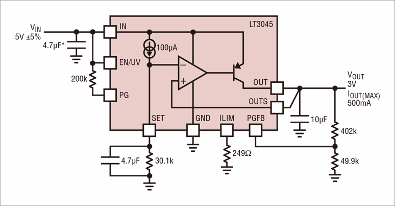
This time, we will make a step-down power supply circuit using the linear regulator LT3045 from Analog Devices.
Design by referring to the following circuit on the top page of the data sheet.
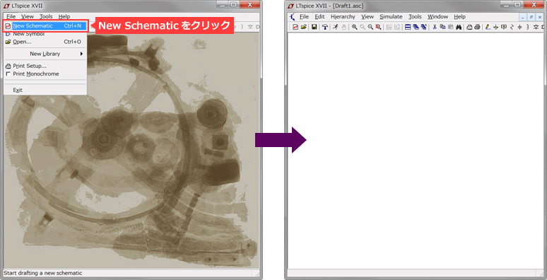
Start from a new schematic
1. Click File > New Schematic and a blank layout screen will appear.
2. Start circuit design!
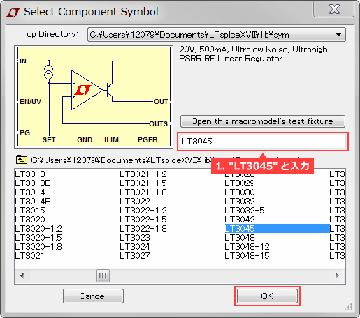
Placing ICs and components
1. Click component and enter "LT3045". If so, click the OK button.

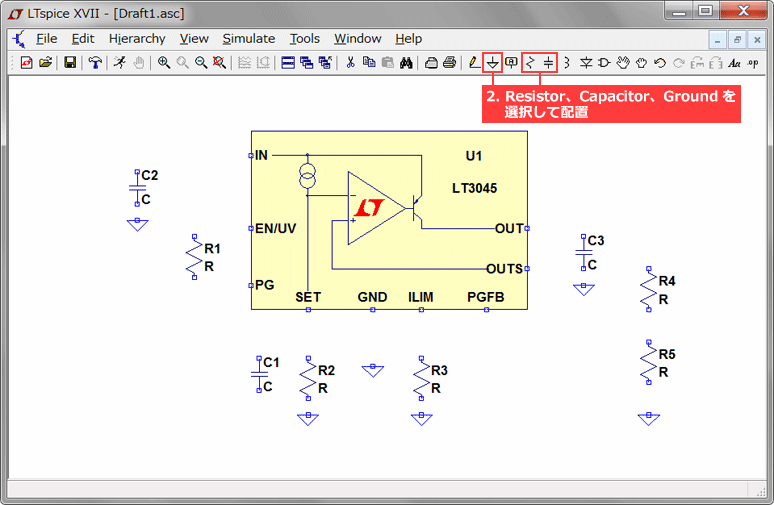
2. Select Resistor, Capacitor and Ground from the toolbar and place them as shown below.
(These can be rotated with Ctrl+R)
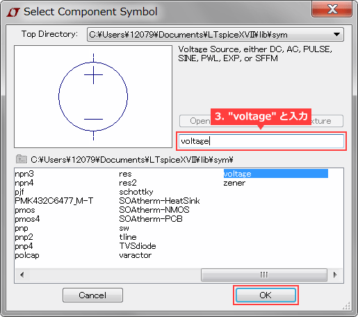
3. Click component again and enter "voltage". Place a Voltage Source.
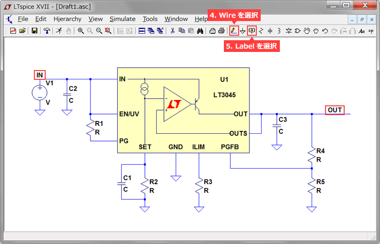
4. Select Wire from the toolbar to wire the circuit.
5. Select Label from the toolbar and name the input and output nodes "IN" and "OUT".
There are two advantages of attaching labels.
- Unlike the node name inside SPICE, it is easy for people to understand by looking at the waveform name (on the simulation result screen).
- Since nodes with the same name have the same potential, they are connected without wiring in complex circuit configurations.
Part parameter selection
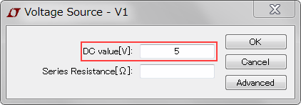
1. Right click on R, C and voltage source (V1) and change the values respectively.
(It can be edited by moving the mouse over the part you want to change and right-clicking.)
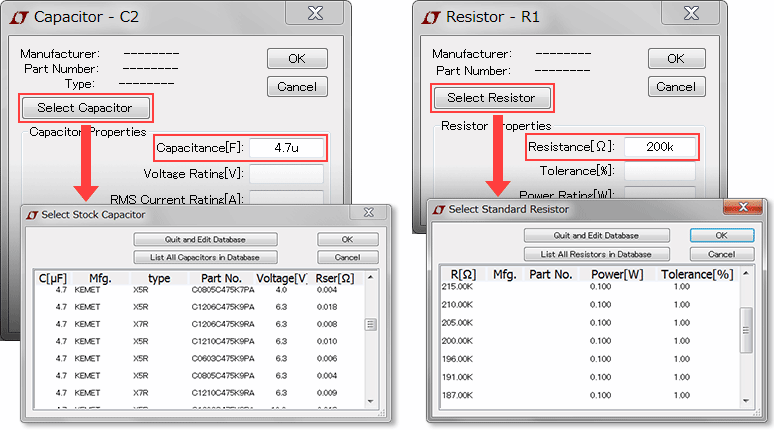
2. Select the part you want to use from the library of parts, if it exists. You can open the parts library by selecting "Select Capacitor" or "Select Resistor" on the parameter selection screen.
※Notes
Unit labels on LTspice are the same as those in the International System of Units, but please note the following three points.
- For 10^6, use MEG(meg) instead of M(m).
- For 1 farad, just enter 1 instead of 1F.
- μ representing 10^-6 is entered as "u" on LTspice.
Run the simulation
Now, the design of the circuit diagram is completed. Now we are ready to run the simulation.
The simulation is executed according to the following procedure.
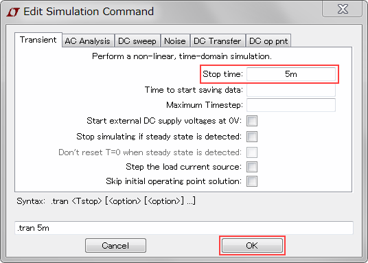
1. Click the Run button on the toolbar to display "Edit Simulation Command".

2. Set the "Stop time" here (5msec here) and click OK to start the simulation.
If you want to know how to set up transient analysis,Transient analysis (.tran)Please refer to the article.
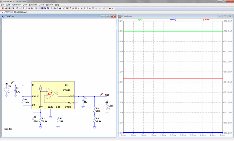
3. Click the point you want to observe in the waveform viewer!
We were able to confirm that the design values of an input voltage of 5 V, an output voltage of approximately 3 V, and an output current of approximately 500 mA were obtained.
bonus
Following the steps above, I created the typical application circuit on the top page of the datasheet.
However, LTspice has a nice feature to call a JIG circuit (sample test).
Please pay attention to the screen where the LT3045 is selected from Component in step 1 of the "IC and component placement" section.
Above the input is a button that says "Open this macromodel's test fixture".
* As of April 2022, LTspice has been upgraded and changed to "Open this macromodel's example circuit".
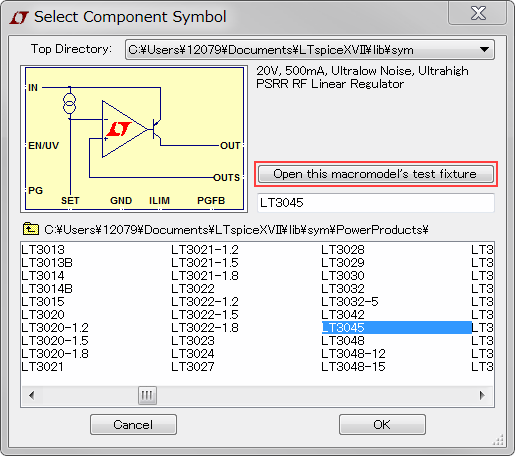
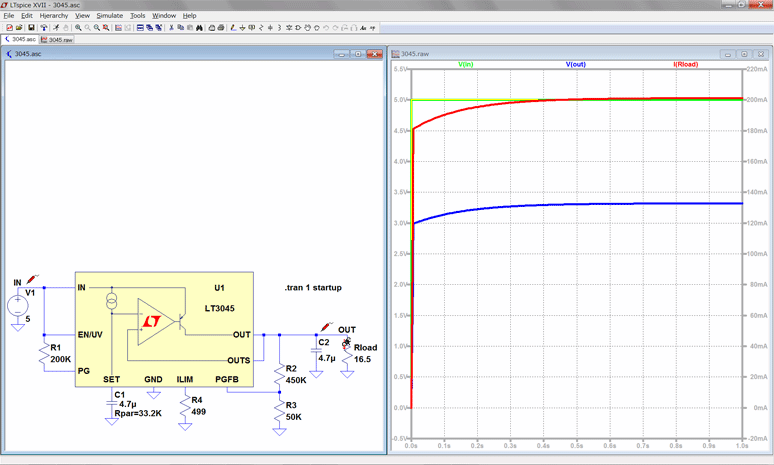
Click here to output a pre-prepared test circuit as shown below.
(Please note that some ICs are not prepared.)
With the test circuit, the simulation can be run by simply clicking the Run button.
It is possible to change the conditions just by changing the parameters of the peripheral parts, so please take advantage of it!
At the end
How was your circuit design with LTspice?
Since the circuit can be designed with simple operations as described above, it is possible to easily check the characteristics.
In addition, since it is easy to change the parameters of peripheral constants, it is the most suitable tool for operation verification before board fabrication.
LTspice is not only easy to use, but also surpasses other tools in terms of simulation model accuracy.
Please try once.
If you want to quickly master how to use it, please select and take the LTspice seminar from the Analog Circuit Technology Seminar.
Click here for recommended articles/materials
List of articles: Let's use LTspice Series
Command Explanation:Master LTspice!
LTspice FAQ: FAQ list
List of technical articles: technical articles
Manufacturer introduction page: Analog Devices, Inc.
Click here for recommended seminars/workshops
Inquiry
If you have any questions regarding this article, please contact us below.
Analog Devices Manufacturer Information Top
Analog Devices Manufacturer Information If you would like to return to the top page, please click below.