

Overview
LC709209F is a product that measures battery RSOC (relative remaining capacity) using Onsemi's proprietary algorithm called HG-CVR2 (Hybrid Gauging by Current-Voltage Tracking with Internal Resistance). The WLCSP12 ultra-small package of 1.48mm*1.91mm allows accurate RSOC measurement, making it ideal for applications such as portable systems. Additionally, when using this product, there is no need for the normally required current sense resistor, which saves space on the board. Another feature is that the power consumption is very low at 2uA.
In this article, we will introduce GUI settings and evaluation methods that can be easily evaluated when considering this product. After inserting the battery, you can simply set a few parameters and start measuring immediately, without the need for long learning cycles that complicate the application development process.
Necessary equipment

・ LC709209F Evaluation Board
・ 1 cell battery
·bread board
・Thermistor
・Several resistors (for battery discharge)
・Charger (for battery charging)
Evaluation procedure
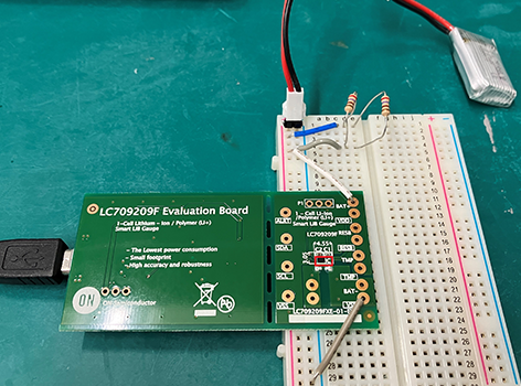
Preparing the evaluation board
1. Connect the evaluation board and computer
2. Connect the evaluation board to the lithium-ion battery and a resistor for discharging (or a charger for charging)
3. Connect a thermistor for temperature measurement
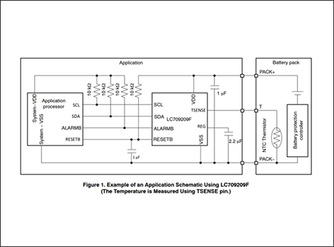
For details, please refer to the LC709209F data sheet and the connection diagram below.
GUI settings (install the evaluation tool FGICTool from the Onsemi website)
Evaluation toolFGICTool
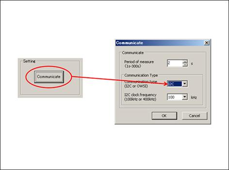
1. After displaying the GUI, enter 100kHz via I2C in the communication type settings, and set the measurement period between 1 and 300 seconds to measure every second.
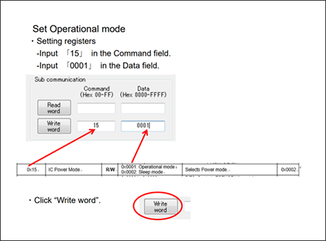
2. Set the operation mode [0x15].
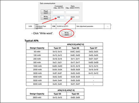
3. Set APA (Adjustment Pack Application) [0x0B].
Enter the current value from the battery specifications and the APA value referring to the chart below. For current values not listed in the table, refer to the data sheet as they can be calculated.
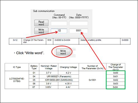
4. Set battery profile [0x12].
Enter the voltage value from the battery specifications and the battery profile value referring to the chart below.
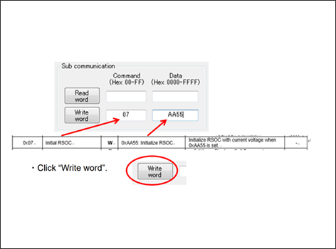
5. Initialize RSOC (Relative State Of Charge) [0x07].
Write AA55 to initialize with the current value.
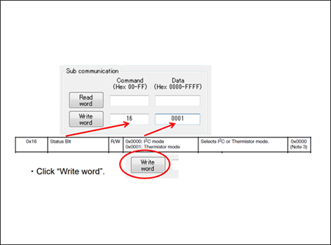
6. Set the thermistor mode [0x16].
When measuring temperature with a thermistor, write the thermistor mode (0001). This setting is not necessary if this LSI receives the cell temperature from the master device via I2C.
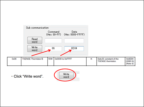
7. Set thermistor B[0x06].
For the B constant, refer to the thermistor's data sheet and set an appropriate value. If there is no need to change the default value (0D34), no writing is necessary.
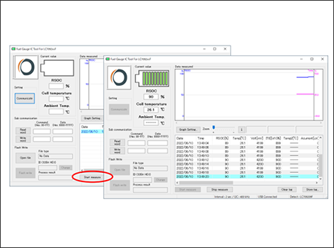
Click “Start measure” to start the evaluation, and click “Stop measure” when you want to end the evaluation. You can also save logs using “Store log”.
Evaluation results

The evaluation results are displayed on the GUI as shown in the figure on the right.
RSOC, temperature, cell voltage, ITE (Indicator to Empty) values, etc. are displayed on the GUI.
Code that is not displayed on the GUI can be read using the Read button.
Please see the table below for register information and the datasheet for details.


Register details

Let's introduce some registers.
・Report information
This is the estimated time until empty. Time To Empty [0x03] or until it is fully charged.
Estimated time Time To Full [0x05] You can check etc.
・Log information
Elapsed time in operating mode after battery insertion Total Run time [0x24, 0x25] or,
Cell temperature value 1 accumulate every minute Accumulated Temperature [0x26, 0x27] Such
You can check.
this Accumulated Temperature register and Total run time register
can be used to calculate the average cell temperature.
・Status and alarm threshold
Contains various alarms and estimated battery status,
Shown on the right Battery Status [0x19] You can check.
Regarding the alarm threshold, the cell voltage high voltage, low voltage threshold,
It is possible to set the cell temperature threshold.
Additional features
Lastly, I would like to introduce two functions added to the LC709209F.
External Reset pin: Supports recovery from emergency situations.
Automatic startup operation: The fuel gauge starts operating with standalone (self) initial register settings after a reset or power-on reset, without any settings from the host MCU.

Application example
・Wearable/IoT devices
·smartphone
・Wireless headset/portable headset
・Portable game player
・USB related devices
Inquiry / Quotation
If you have any questions about this product or would like a quote, please contact us using the form below.
Onsemi Manufacturer information Top
If you want to go back to ONSEMI Manufacturer Information Top, please click below.