- Semiconductor BusinessHOME
- Products and Services of Macnica,Inc.
-
technical information

-
Events and Seminars
- Handling Manufacturer
- Support
- Inquiry
- Click here to purchase products
- Semiconductor business e-mail magazine registration
![]()
![]() Narrow down by specifying conditions
Narrow down by specifying conditions
現在2189件がヒットしています。check
![[Passive Components (LC) Basic Lecture Series] LC Basics ~ Part 6 Types and Features of Capacitors ~](/business/semiconductor/articles/141234_wurth_article_cover_ver3.png)
Inductors and capacitors are essential components in electronic circuits. I will explain the basic role of its operation.
The contents of this time will be Part 6 "Types and features of capacitors".
If you want to see other articles, there is a summary page, so please take a look there.
Condenser type
Figure 1 shows typical capacitor types.
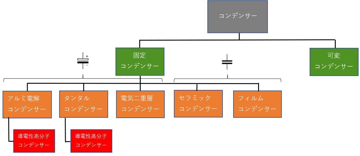
Figure 1: Types of capacitors
They can be broadly classified into fixed capacitors and variable capacitors, but here we will explain the fixed capacitors, which are often used.
Polarity of the capacitor
Capacitors can be classified into polar and non-polar. Polarized capacitors have a fixed + side and - side, so if they are reversed, it will cause a malfunction. Therefore, it cannot be used for alternating current.
In Figure 1, aluminum electrolytic capacitors, tantalum capacitors, electric double layer capacitors, and conductive polymer capacitors are applicable. Polarity can be identified by appearance such as the length of the terminal and the color of the top of the part, as shown in the example in Fig. 2.
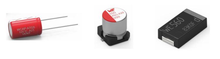
Figure 2: Appearance of a polarized capacitor
A non-polar capacitor does not have a fixed + side and - side, so it does not matter which side is + as long as it is within the withstand voltage range, so it can be used with alternating current. In Figure 1, ceramic capacitors and film capacitors are applicable.
Features of aluminum electrolytic capacitors
The biggest feature of aluminum electrolytic capacitors is their large capacity. As explained in"Basics of LC - Part 4 What is a capacitor?", the capacity of a capacitor is determined by the area of the electrodes used, the dielectric constant of the dielectric, and the distance between the electrodes. Although the dielectric constant of the dielectric is not large at 8 to 10, it has a high withstand voltage and can be made thin, and by expanding the electrode area through etching processing, a high capacitance can be obtained.
Figure 3 shows the structure of an aluminum electrolytic capacitor.
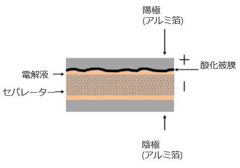
Figure 3: Structure of an aluminum electrolytic capacitor
The disadvantage of aluminum electrolytic capacitors is that their ESR is large, so the allowable ripple current cannot be so large. The frequency characteristics are bad, and it is necessary to consider the life. As for life, the concept is called double speed at 10 °C. As shown in Table 1, for example, if a capacitor is selected for 5,000 hours at 105 °C, its life will be 10,000 hours at 95 °C.
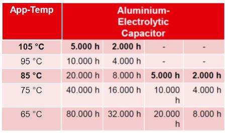
Table 1: Lifespan of aluminum electrolytic capacitors
Features of tantalum capacitors
Tantalum capacitors have almost the same structure as electrolytic capacitors and are often used in the same way. In this section, we will explain their features in comparison with aluminum electrolytic capacitors.
The advantages and disadvantages when compared with aluminum electrolytic capacitors are as follows.
merit
・The size per capacity can be made smaller.
・Excellent frequency characteristics
・ ESR is small
・Long life
Demerit
・Capacity cannot be increased
・Low pressure resistance
・Breakdown in short mode
In particular, it is necessary to pay attention to the fact that it fails in the short mode, and there is a risk of ignition, so care must be taken not to apply reverse voltage or overvoltage.
Features of electric double layer capacitors
Also known as a supercapacitor, there are products with a capacity exceeding 1000F, which is much larger than general capacitors. It is positioned between a capacitor and a secondary battery, and Fig. 4 shows the relationship between power density and energy density.
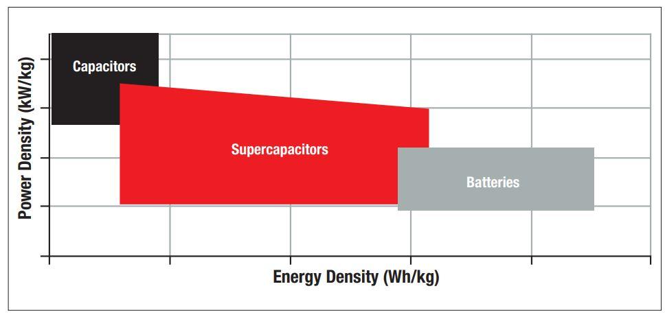
Figure 4: Power density and energy density of supercapacitors from Wurth Elektronik Product Portfolio
It has features such as very low ESR and high cycle life. Since the withstand voltage is as low as several volts, it must be connected in series for use at higher voltages. A balance circuit is required to prevent the voltage from becoming unbalanced due to variations in capacitance between elements.
Features of conductive polymer capacitors
A conductive polymer capacitor is a capacitor that uses a conductive polymer for the cathode of the aluminum electrolytic capacitor structure shown in Figure 3, and a tantalum capacitor has a similar structure. It has a small ESR and a high rated ripple current, and has the feature that there is almost no capacitance change due to temperature or DC bias that is seen in ceramic capacitors. It cannot be used for high voltage applications because there are no products with higher rated voltages. The service life is longer than that of aluminum electrolytic capacitors, and as shown in Table 2, the concept is called 20 °C 10 times faster.
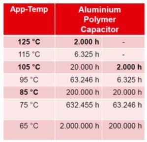
Table 2: Lifespan of Conductive Polymer Capacitors
Features of film capacitors
Film capacitors have the following excellent features
・High withstand voltage
·Long life
·High precision
・Temperature characteristics, DC Almost no bias characteristics
However, it is a capacitor that cannot have a high capacity because the dielectric constant is low. As a dielectric in film capacitors PP, PET, PPS, PEN There are types such as , and they have different features, so you need to select according to your needs.
Features of ceramic capacitors
Ceramic capacitors are characterized by high dielectric constant of the ceramic used, small size and high capacity. In addition, since the ESR is very small, it can handle high ripple currents and has excellent frequency characteristics. Ceramic capacitors are broadly classified into those for temperature compensation and those for high dielectric constant. Although high capacitance cannot be obtained for temperature compensation, there is almost no change in capacitance due to usage conditions such as temperature characteristics and DC bias characteristics.
These considerations are necessary for high dielectric constant systems. Figure 5 shows an example of capacitance change.
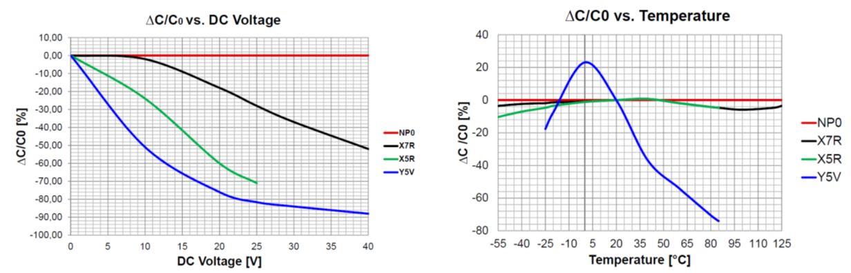
Figure 5: Example of capacitance change of a ceramic capacitor
NP0 is for temperature compensation, and it can be seen that there is almost no change in capacitance even with DC bias or temperature changes. Other than that, it becomes a high dielectric constant system, and although the rate of change differs depending on the characteristics, the capacitance changes.
Information on simulation tools
Please click the image above. Link to the simulation tool "RED EXPERT" page.
If you would like to purchase from Macnica-Mouser, please click here
Ult Electronics products are available for purchase at Macnica-Mouser (Macnica-Mouser), a mail order site for semiconductors and electronic components.
If you want to buy a product in a hurry, you can consider Macnica-Mouser.
Inquiry
If you have any questions regarding this article, please contact us below.
Würth Elektronik Manufacturer Information Top
If you would like to return to the Würth Electronics Manufacturer Information top page, please click below.