- Semiconductor BusinessHOME
- Products and Services of Macnica,Inc.
-
technical information

-
Events and Seminars
- Handling Manufacturer
- Support
- Inquiry
- Click here to purchase products
- Semiconductor business e-mail magazine registration
![]()
![]() Narrow down by specifying conditions
Narrow down by specifying conditions
現在2175件がヒットしています。check
![[Basic lecture series on passive components (LC)] Selection of LC -Part 3 AC loss of inductor-](/business/semiconductor/articles/139711_wurth_article_cover_ver2.png)
Inductors and capacitors must be selected according to the application. We will explain the points that need to be considered for selection.
The content of this time is Part 3 “AC loss of inductor”.
If you want to see other articles, there is a summary page, so please take a look there.
Does it heat up even with no load?
We have already touched on AC loss, but this time we will explain the concept and what points should be selected.
Inductors in power circuits and power modules may generate heat even without a load. This may be due to AC losses in the inductor.
Figure 1 shows the main loss components of an inductor.
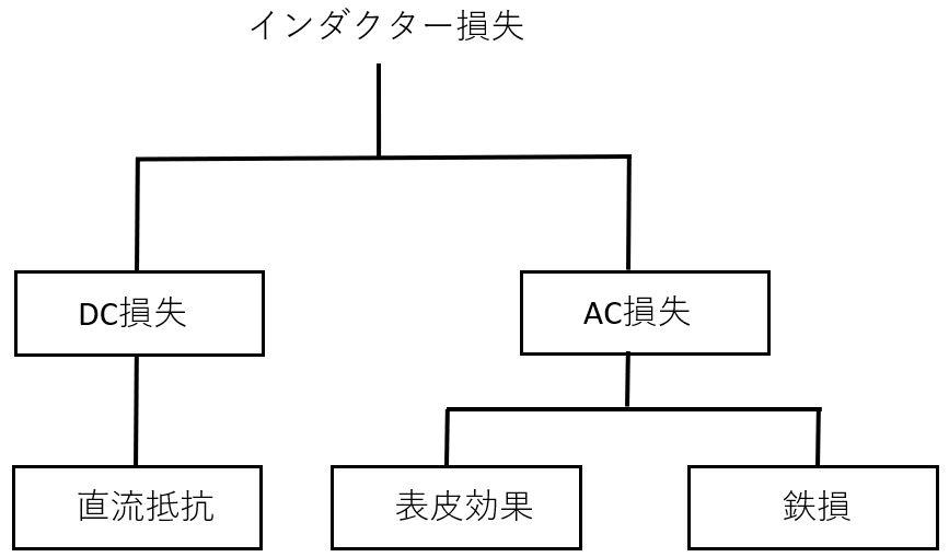
Figure 1 Loss component of inductor
In Figure 1, iron loss is determined by AC components such as the voltage and frequency applied to the inductor, so it is almost unaffected by the load current.
The DC resistance component including the skin effect increases with the square of the load current.
If the heat generation is large even when there is no load, it is necessary to take this point into account when considering the operating conditions and the parts to be selected.
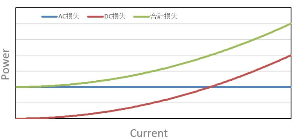
Fig. 2 Relationship between current and loss
図2は電流値とDC損失、AC損失のイメージ図です。このイメージのケースでは無負荷時でも最大負荷時の1/3の損失が発生しています。
“Wanting to reduce loss = a product with low DC resistance” does not necessarily follow.
What is iron loss?
Iron loss, which is the loss component of the iron core (core material) used, is mainly caused by hysteresis loss and eddy current loss.
This was described in LC Selection ~ Part 1 Power Inductor Selection ~, but since it is difficult for the user to calculate, here we will explain what factors increase or decrease.
The characteristics of the core material used are an important factor, but in most cases it is not disclosed, so we do not consider it here and assume that it is a family product using the same core material.
Factors related to iron loss
・Inductance
Iron loss is reduced by increasing the value. However, the DC resistance increases, so it is necessary to check which is the dominant loss and adjust accordingly.
·size (volume)
Iron loss is reduced by increasing the value. In this case, even with the same inductance, a thick wire can be used, so the DC resistance is also reduced and the loss is greatly reduced.
It should be adjusted for the size and loss that your application can tolerate.
・Specifications (applied voltage × time)
Iron loss increases as the value increases. I will explain using Figure 3.
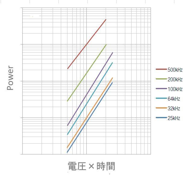
Fig. 3 Relationship between voltage x time and loss
Figure 3 shows the relationship between applied voltage x time and loss.
From this, it can be seen that at 500 kHz, if the applied voltage x time is doubled, the core loss will increase about five times. . For example, if the same inductor is used to generate 2.5V from 5V and 5V from 10V at 500kHz, the iron loss will increase by about 5 times.
From these factors, it can be seen that as the voltage increases, iron loss increases and the ratio of AC loss increases. In this case, even if the DC resistance increases, selecting a product with a high inductance may reduce the total loss.
If it is permissible, it is possible to reduce the loss by considering a product with a large size (volume).
Conversely, if the voltage is low, the AC loss ratio is low, and lowering the DC resistance may directly lead to loss reduction.
What is the skin effect?
The skin effect is a phenomenon in which, when an alternating current flows through a conductor, the higher the frequency, the more concentrated the current flows on the surface, and the less it flows in the center, resulting in a higher alternating current resistance.
Figure 4 shows an image of the skin effect. The red part is the part where the current is flowing. In direct current, the current flows uniformly in the conductor, but as the frequency increases, almost no current flows in the center.
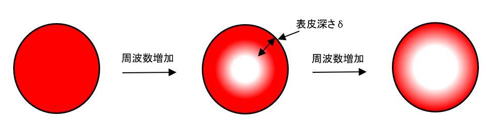
Fig. 4 Skin effect
δ is the skin depth, which is 1/e (36.8%) of the surface current density.
In case of copper wire, it is calculated by this formula.
δ=2.09/√f [mm]
When using a large current, the copper wire is made thicker to lower the DC resistance, but when the frequency is raised, the resistance value increases due to the skin effect.
Due to this factor, loss may be reduced by lowering the frequency when using a large current.
Summary
When inductors are used in AC circuits, AC losses occur in addition to DC losses. In this article, we will discuss AC losses.
If the heat is generated under no load or near it, it may be reduced by increasing the inductance or size.
At high currents, the skin effect can also occur, so it may be possible to reduce the loss by adjusting the frequency.
Since it is difficult to calculate AC loss by calculation, we recommend using simulations, etc., in addition to evaluation with actual equipment.
If you want to estimate DC loss and AC loss with Redexpert, please refer to "Points to note when selecting components 3" in the article "Selecting an LC - Part 1 Selecting a Power Inductor".
Information on simulation tools
Please click the image above. Link to the simulation tool "RED EXPERT" page.
Inquiry / Quotation
Click here to buy now
Wurth Electronics Manufacturer Information Top
If you would like to return to the Wurth Electronics manufacturer information top page, please click below.