- 半導体事業HOME
- マクニカの製品・サービス
-
技術情報

-
イベント・セミナー
- 取扱メーカー
- サポート
- お問い合わせ
- 製品購入はこちら
- 半導体事業のメルマガ登録
![]()
![]() 条件を指定して絞り込む
条件を指定して絞り込む
現在2175件がヒットしています。check
インダクター、コンデンサーは用途に合わせた部品選定が必要です。選定のために考慮が必要なポイントを解説します。
今回の内容は、Part1 “パワーインダクターの選定”になります。
他の記事もご覧になりたい方はまとめページがありますので、そちらをご覧ください。
パワーインダクターの選定の流れ
電源回路に使用するパワーインダクターの選定において考慮しなければならないポイントがいくつかあります。今回は3つの注意点について解説します。
一般的な設計の流れとしてこのようなケースが多いのではないでしょうか。
・電源ICの選定
・スイッチング周波数の決定
・インダクタンスの決定
・インダクタンス、定格電流から部品選定
今回は入力VIN=12V、出力VOUT=3.3V、負荷電流IOUT=4Aの仕様を例に考えてみます。
関連記事として”スイッチング・レギュレーターの設計方法”及び”降圧型DC/DCコンバーターの定数計算と注意事項”もご参照ください。
電源ICはLT8640、スイッチング周波数は1MHzを選択します。
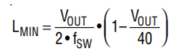
インダクタンスはデータシート記載の下記計算式からLmin=1.51μHとなります。
部品選定時の注意点1:インダクタンス変化
必要なインダクタンスが決定したら部品選定になりますが、インダクタンスを大きくすると形状が大きくなるため必要十分のインダクタンス値を選択します。
一般的にE12系列の定数がラインナップされていることが多いため、今回は2.2μHを選択します。
E系列については関連記事として”豆知識:抵抗やキャパシターの値”もご参照ください。
インダクターは確認するべきポイントが2つあります。
・インダクタンス公差
・直流重畳特性
まず公差について考えます。パワーインダクターのほとんどは20~30%の公差を持っています。2.2μH±20%の場合、下限は1.76μHとなりますので電源ICの要求する最小値を満たします。
1.8μHを選択した場合は公差の下限に近いと要求を満たせません。
次に直流重畳特性について考えます。この特性については使用されているコア材が重要になります。
ここでは広く流通しているフェライト系とメタル系について比較してみます。
インダクタンスが同じで定格電流が近いウルトエレクトロニクス社の2種類のインダクターの特性を図1に示します。
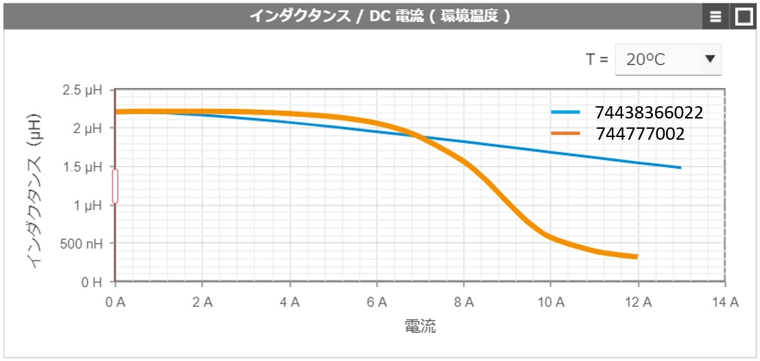
図1:直流重畳特性比較
744777002はフェライト系のコア材を使用しています。特徴はインダクタンスの変化が少ない期間が続き、減少し始めると急峻に低下していくことです。
フェライト系を選択する場合は使用領域がインダクタンス変化の少ない期間であるものを選択します。
74438366022はメタル系のコア材を使用しています。こちらは電流を増やすと緩やかに右肩下がりにインダクタンスが低下していることがわかります。
メタル系は磁気飽和しにくい特性であることがわかります。
このインダクタンスの変化はコア材の透磁率μの変化するために起こります。電流を増やすとインダクタンスがさらに低下し磁気飽和を起こしてしまいます。
インダクタンス変化は動作温度によっても変化します。前述の2種類のインダクターの100℃におけるインダクタンス変化を図2に示します
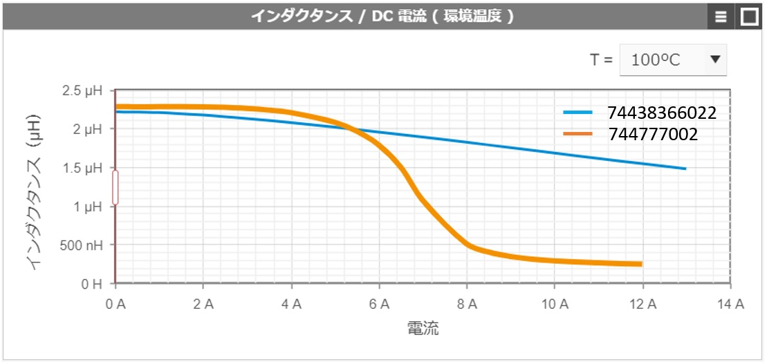
図2:直流重畳特性比較(100℃)
図2からメタル系は温度変化があまり見られませんが、フェライト系はインダクタンスが低下を開始するポイントが小さくなっていることがわかります。
高温環境で使用するアプリケーションでは温度特性も考慮する必要があります。
部品選定時の注意点2:過電流の考慮
パワーインダクターの選定は短絡等の異常時も考慮するべきポイントです。ほとんどの電源ICには過電流保護機能が備わっています。
しかしながらインダクターが磁気飽和してしまうと図3のように急峻な電流変化が発生します。
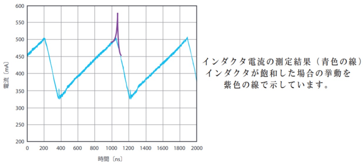
図3:磁気飽和時の挙動
アナログデバイセズ社、Analog Dialogueより
特殊な電源ICを除いて急峻な電流変化に応答できず、期待する動作が得られないことが起こりえます。
LT8640では図4の値で過電流保護値が規定されていますので、12.5A流れても飽和しないインダクターを選定します。

図4:LT8640 過電流保値
アナログデバイセズ社、LT8640データシートより
今回検討した744777002は12.5A時にインダクタンスは約-90%まで低下するため、この仕様で使うには適していません。
74438366022は12.5A時でも約-20%の低下にとどまるため、使用可能と考えることができます。
部品選定時の注意点3:温度上昇
パワーインダクターは周囲温度 + 自己上昇が動作温度範囲内で使用する必要があります。
電源回路に使用するパワーインダクターの自己上昇についてはDC損失とAC損失を考慮する必要があります。
DC損失についてはインダクターの電流定格値と使用する電流によって計算することができます。
関連記事として”LCの基本 ~Part3 インダクターの特性”もご参照ください。
しかしAC損失をコア材の特性や巻線の情報など開示されていない内容を必要とするため、計算することは困難でシミュレーションツールを活用します。
ウルトエレクトロニクス社の”REDEXPERT”を使って、この仕様における74438366022のAC損失のシミュレーション結果を図5に示します。
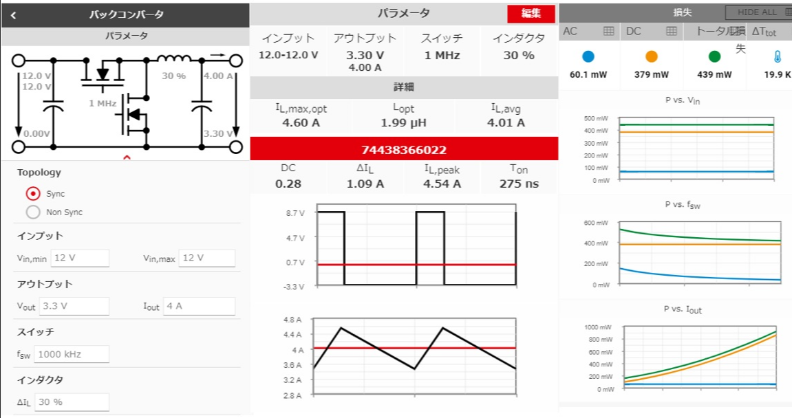
図5:AC損失シミュレーション
“REDEXPERT”では仕様を入力し部品番号を指定すると、DC損失とAC損失の値とそれによる自己上昇が表示されます。
今回の仕様では約20℃の自己上昇であることが確認できます。
シミュレーションツールのご案内
上記画像をクリックください。シミュレーションツール「RED EXPERT」をご案内します
お問い合わせ / お見積もり
本製品に関してご質問、見積もりなど希望がありましたら以下より問い合わせください。
すぐに購入を希望の方はこちら
ウルトエレクトロニクス メーカー情報Topへ
ウルトエレクトロニクスメーカー情報Topページへ戻りたい方は、以下をクリックください。