- Semiconductor BusinessHOME
- Products and Services of Macnica,Inc.
-
technical information

-
Events and Seminars
- Handling Manufacturer
- Support
- Inquiry
- Click here to purchase products
- Semiconductor business e-mail magazine registration
![]()
![]() Narrow down by specifying conditions
Narrow down by specifying conditions
現在2184件がヒットしています。check

In the previous tutorials, we covered the issues of proper filtering, stability, and protection required when using power modules to build a complete DC-DC power system. This tutorial will focus on a unique problem that arises in systems that include power modules in their loads.
A DC-DC module load was once simply viewed as a black Box with only voltage and current.Over the years, however, loads have become more complex and today have different characteristics that are described as power distribution networks (PDNs).Therefore, it is necessary to understand the load behavior in detail and determine its effect on the DC-DC module.
For example, the response of the module's control loop is affected by load, which can lead to stability problems in its regulation function.It can also adversely affect the transient response of the module.
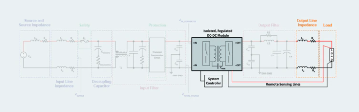
Figure 1: When designing a system, it is always necessary to consider the load (the orange dashed line in the figure).
Basic load types and their effects on control loops and transient response
There are mainly three types of loads: resistive loads, combined loads of resistance and reactance, and when DC-DC converters are placed as loads.A resistive load is the simplest load and has no effect on the control loop or transient response of the DC-DC module.
Loads that combine resistive, inductive, and capacitive elements certainly have an impact on the control loop stability and transient response of DC-DC modules. If the load of the DC-DC module is a converter module, the effect is not so great, but inthis case, the control loop stability and transient response of the preceding module depend on the control loop characteristics of the following module.Besides these main load types, there are special loads that should be carefully analyzed.
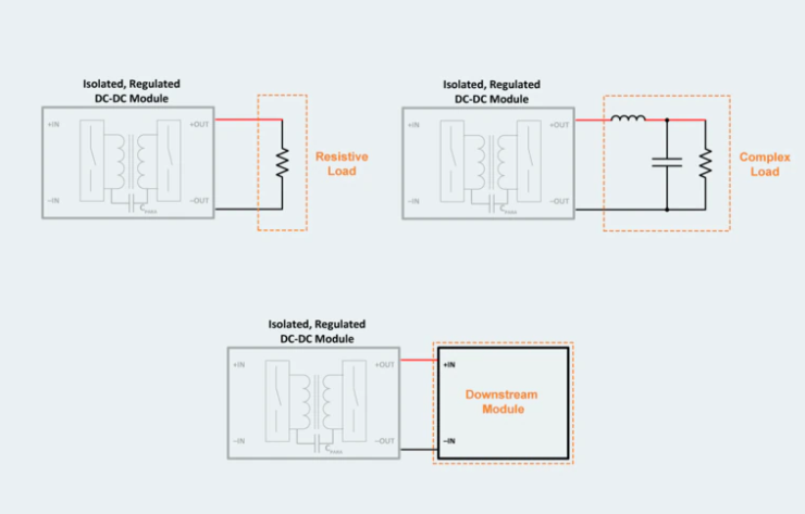
Figure 2: Three basic types of load: resistive load, combined resistive and reactive load, and power module connected as load
EMI and performance issues caused by inductive loads
Inductive loads present a problem when turning off the DC-DC module.Figure 3 is an example of a simple inductor and series switch to illustrate the nature of an inductive load. When the switch opens, it breaks the current path from the module to the inductor,which acts to block the current from changing, resulting in a large negative voltage spike.
This phenomenon can cause high frequency noise pulses and arcing in open switches.Voltage spikes are applied to the output of the DC-DC module (all circuits connected to the power bus) andaffect the operation of the module, as well as the EMI and other performance of the module.The solution is to add a freewheeling diode in parallel with the inductive load to create a discharge path for the energy stored in the inductor.
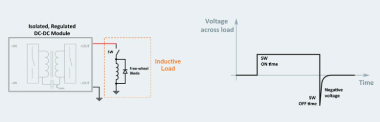
Figure 3: A very large negative voltage spike at switch-off, typical of inductive loads. The impact on the power supply system is large.
Power averaging for efficient handling of pulse loads
A pulsed load is a load with very high current peaks and short duration, which poses a challenge in the design of DC-DC systems.When designing a power system for such loads, the easiest thing to do is to choose a power module that can supply the peak value of the pulsed current as the maximum load. However, although this method has no problem functionally, it increases the weight and cost of the power supply module itself, filters, and heat dissipation parts.
Power averaging techniques allow for smaller, lower cost system designs.Average power can be expressed as a peak load and the ratio of on-time to off-time.When designing a power averaging system, a smaller DC-DC module can be used and alarge energy storage element can be used to reduce the voltage drop during the on-time of the load duty cycle. Make sure it stays within specification.In this way, instead of over-designing the worst-case system, you can design an optimal system that meets the actual power requirements.
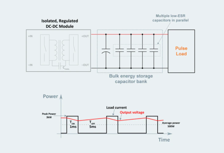
Figure 4: Power averaging techniques can be used to optimize a DC-DC system for short, high-current pulse loads.
There are a few considerations when choosing a power module for power averaging. First, the output current and power of the power module must be limited so that the load can be supplied from a large capacitor placed at the output of the power module during peak pulse loads.
Also, the pulse load characteristics require a lot of energy storage, so the DC-DC module must start up and work properly with a large output capacitor. Large output capacitance can also affect the stability of the module and should be considered in system design.
There are three important considerations when choosing a bulk capacitor to incorporate into a power delivery network (PDN). First, the voltage rating should be about 140% (or more) of the system's operating voltage. Second, choose a capacitor with a proper temperature profile so that system reliability is not adversely affected in hot environments. Finally, consider the balance between these performances and an acceptable physical size.
Parallel connection of modules for high-power loads
The greatest advantage of a DC-DC system consisting of modules is its high scalability.The power supply modules are capable of current sharing and can be connected in parallel to prepare for failures.They are more reliable and can deliver higher power without introducing new discrete designs.
When connecting power modules in parallel, you may not need to worry about the control interaction of each module, but there aretwo main things to be aware of.
The first is that when connecting multiple modules, power derating may be required compared to using them individually.For example, multiple connected modules may not start at the maximum rated load of a single module.
Second, external control circuitry is required to ensure that the entire system does not haltwhen shutting down or restarting a failed module.
Current share of modules connected in parallel
To maximize the performance of paralleled modules, load them equally.This ensures even thermal stress on each module, maximizing overall system reliability.The simplest method of current sharing is to use droop characteristics.When passing current to the load, the output voltage of the module decreases as the current value increases, promoting current balance between modules.
Although it has a complicated configuration, it also has active current share control that monitors the output current of each module.
Noise decoupling improves power supply quality for paralleling modules
An input/output filter is required when connecting modules in parallel.Prevents noise currents generated by a module from flowing and interfering with neighboring modules.When noise currents flow freely between parallel circuits, serious problems can occur that affect the entire system.
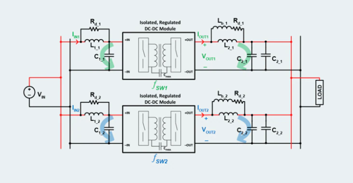
Figure 5: Switching frequency noise (green and blue arrows) is reduced by the input and output filters of each parallel module, preventing beat noise from circulating in the parallel circuit and destabilizing the system.
System stability can be affected by the addition of low frequency components of switching noiseto the overall system switching frequency noise profile. Such a beat frequency occurs because there are individual differences even if the modules connected in parallel are of the same type and of the same model.Ideally, if all modules in parallel had the same switching frequency, thenoise would add up to create a wide single-frequency ripple, but the reality is more complicated.
There is another reason why you should put input and output filters on each module.Normal noise from one module can be transferred to other modules in parallel, causing large variations in module behavior even without a change in load.For designing output filters, see the second tutorial in this series.
Fault tolerance and redundant configuration by parallel connection
Fault tolerance is improved by connecting modules in parallel to create a redundant configuration.This greatly improves the reliability and stability of DC-DC power systems with a small cost increase.An N+1 redundant system can be configured by adding one module to the system and connecting them in parallel.Furthermore, by connecting multiple modules in parallel, an N+M redundant configuration is realized.
The specific configuration varies by application, but the basics are the same.OR the outputs of the modules to prevent the whole from shutting down in the event of a fault or short circuit.There are two ways to do this, put an active circuit using diodes or MOSFETs in series with the output of each module.A diode in series disconnects the output when the module is shorted, leaving the rest of the parallel connections unaffected.
However, if the output current flows during normal operation, power loss will occur due to the forward voltage drop.To reduce losses, increase the temperature of the diode, since the temperature coefficient of the forward voltage drop is negative.To further reduce losses,an active circuit using MOSFETs instead of diodes can achieve the same function as diodes while suppressing efficiency loss.
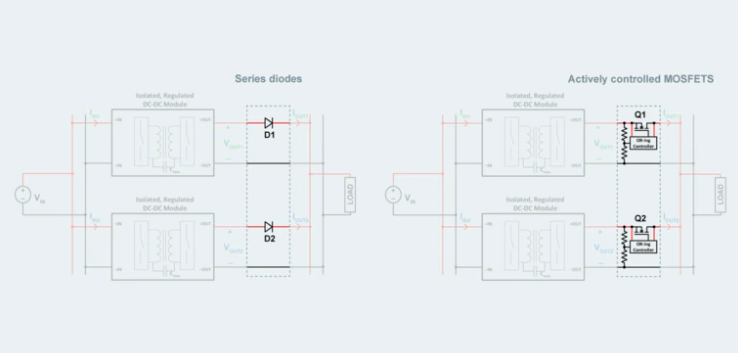
Figure 6: There are two methods of ORing modules so that a single module failure does not bring down the entire system. Insert an active circuit using a diode or MOSFET in series.
Power supplies composed of modules are evolving
Designing a discrete solution becomes more cumbersome each year as the load demands on the power supply steadily increase.More power, higher power quality, higher efficiency, scalability, tight design schedules and many other challenges.A power supply design approach that combines modules has a distinct advantage in dealing with these changes.
But that means adopting new ideas and introducing new tools and technologies.Power supply modules are steadily becoming smaller, more efficient, and more powerful,so taking the time to understand the design methodology for combining modules is extremely valuable.