- Semiconductor BusinessHOME
- Products and Services of Macnica,Inc.
-
technical information

-
Events and Seminars
- Handling Manufacturer
- Support
- Inquiry
- Click here to purchase products
- Semiconductor business e-mail magazine registration
![]()
![]() Narrow down by specifying conditions
Narrow down by specifying conditions
現在2191件がヒットしています。check
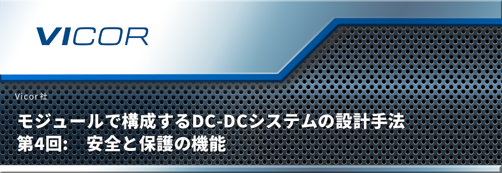
The previous tutorials have detailed practical considerations when designing a power distribution network (PDN) using power modules. Now that we have selected the appropriate DC-DC module, designed the input and output filters for the module, and ensured the overall stability of the system, it is time to consider safety. Fuses and transient suppression circuitry must be added to insure the system against catastrophic failures without compromising performance or reliability.
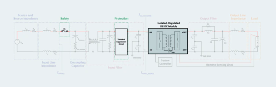
Figure 1: A well-designed power system has protection features. Fuses limit overheating damage and isolate failed systems.A transient suppression circuit controls surges and spikes to prevent power module damage and system instability.
Fuse requirements and functions
The first step in selecting a fuse is to check the safety agency approval conditions (CofAs) in the documentation provided by the DC-DC module manufacturer. Review current documentation to select fuse type to ensure meeting safety agency CofAs.
Fuses are an important safety feature of the system and have two main functions.
・Suppression of damage due to overheating caused by overcurrent or short circuit
・Isolation of failed subsystems
First, if the system has no fuses, overheating damage due to a catastrophic failure can be extremely catastrophic. Depending on how much current the fault draws, the printed circuit board may be charred and all components destroyed completely. Fuses not only prevent fires, but also aid in failure analysis by protecting the system from spreading fire in the event of a failure.
Second, fuses prevent system downs by isolating a failed subsystem from the overall system. In order for the fuse to perform both functions satisfactorily and meet safety agency requirements, each power module must have its own fuse on the input side. In the system of Figure 2, if either the non-isolated PoL converter or its associated input circuitry fails, the corresponding fuse blows, allowing the rest of the system to continue operating.
Figure 2: Fuse placement for a power system with three DC-DC modules. Each module has a protective fuse.
Fuse selection
The first and most important parameter to consider when choosing a fuse is the rated current value. It is important that the rated current value is greater than the maximum continuous operating current value of the system to be protected. For regulated DC-DC modules, the conditions for maximum continuous operating current are the minimum input voltage and the maximum load.
To accurately determine the maximum continuous operating current value, consider this condition and the conversion efficiency of the module. Fuse manufacturers typically recommend a 25% to 50% derating when calculating the current rating of a fuse. This is done in consideration of the aging deterioration of general fuses, but it is also to prevent fuses from frequently blowing and requiring replacement work.
After determining the amperage rating of the fuse, the next step is to consider the environmental conditions in which the system will operate. Fuse manufacturers' datasheets have temperature derating charts like Figure 3. Depending on the application and the expected ambient temperature, the rated current value of the fuse should be adjusted.

Figure 3: Temperature derating chart for common fast-acting fuses. Derating is required when used at temperatures above 25°C.
The rated current value indicated by the fuse manufacturer is based on an ambient temperature of about 25°C, but the higher the ambient temperature, the lower the actual rated current value of the fuse. If the temperature exceeds 25°C, the amperage at which the fuse trips will decrease, so derating on this chart will result in a fuse with a higher amperage rating in the system. A similar recalculation is performed when the temperature is low. If the ambient temperature is typically below 25°C, select a fuse with a correspondingly lower current rating.
The rated voltage value is also an important safety item. Prevents system damage from arcing by reliably breaking the circuit when the fuse trips. Choose the DC voltage rating of the fuse to match the maximum voltage that the system can tolerate. That is, it must be equal to or greater than the maximum voltage for your application.
Next, consider the fuse's maximum breaking current rating, or breaking capacity. It is the maximum fault current value that a fuse will interrupt when overloaded at its rated voltage, which must be equal to or greater than the maximum short-circuit current of the circuit it protects. This setting isolates the faulty part from the system in the event of an overcurrent without damaging the fuse's own package. A failure that damages the fuse package when the fuse blows is a dangerous failure mode because other adjacent components are likely to be damaged as well.
Note that the fuse rated voltage and breaking current specifications may vary depending on whether the application is an AC or DC system. Read and understand the specifications on the fuse datasheet.
Nominal fusing I2t value
Next, consider the nominal blown I 2 t value of the fuse to accommodate the scenarios in which the fuse should not trip. For example, a DC-DC system charges capacitors at start-up, which can draw large inrush currents. These peak currents can also be caused by transients external to the system.
The nominal melting I 2 t value of a fuse indicates the thermal energy that melts the elements inside the fuse. For example, in DC-DC converter applications, pulsed current overloads occur frequently and can exceed the current rating of the actual selected fuse.
To determine the value of this energy and select an appropriate fuse, consider the possible current waveforms and their energies in joules. Figure 4 shows two representative waveforms and I 2 t for each pulse. Choose a fuse with an I 2 t value rated above this value so that the amount of energy required here will not trip the fuse.
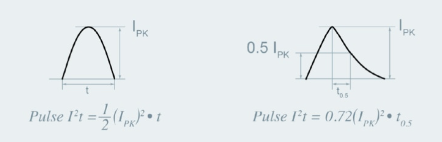
Figure 4: Typical pulse shape and I2t calculation formula—sine wave (left) and lightning surge waveform (right)
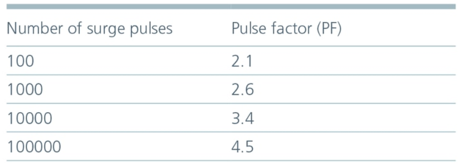
If the number of surge pulses applied is large,Pulse factor is used to increase design margin and reduce fuse replacement over the life of the system.I calculated from the waveform2Real I2Consider it as a t-value.
Other Fuse Considerations
There are other important considerations when designing fuses for power systems. Here are some of the things you should pay particular attention to:
• The fuse should be installed on the non-grounded side so that the connection to the low potential is maintained even if the fuse blows.
• Modern cooling solutions require relocated fuses.
For example, in liquid immersion cooling, do not immerse the fuse. This is because if the temperature of the fuse element is affected by the cooling liquid, the temperature rise may not be sufficient even in an overload condition and the fuse may not open.
・Although it depends on the size and rating of the fuse used, the thickness of the current-carrying conductor and PCB wiring should be 150 to 200% of the rated current of the fuse.
It must be able to be safely energized.
Also consider the allowable temperature rise, depending on applicable safety standards.
・When two power supplies are connected in series, the connection point is used as a common ground, and power is supplied to one power supply in the latter stage by the positive/negative wiring of the output,
Both positive and negative terminals must be protected with separate fuses.
In this case, both positive and negative lines can cause line-to-ground faults, so both sides must be protected.
Transient suppression circuit
In all applications, power modules are subject to adverse environmental conditions during their lifetime. Power systems and power modules in particular must withstand surges and spikes beyond their normal operating range.
Spikes and surges are typically caused by switching inductive loads, speed changes of motors in the system, fault isolation, and power interruptions. Spike transients are usually very short in duration, but the voltage peaks can be quite high.
On the other hand, surges have slightly lower peak voltages, but can last for a long time.
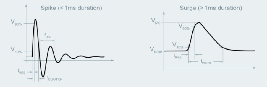
Figure 5: Shapes of transient voltage spikes and surges
To accommodate spikes and surges, consider the type of application and any standard requirements that govern these transients. Once those numbers are known, design a two-stage protection circuit as shown in Figure 6 and place it at the input of the power module.
The first stage uses a transient voltage suppressor (TVS) diode to attenuate fast transient energy on the order of 100µs to suppress spikes. This protects against high voltage, low energy spikes. The energy is integrated by the LC filter connected in the latter stage.
There are four main parameters to consider when choosing a TVS diode. Reverse breakdown voltage, clamping voltage, and peak pulse current, which are the maximum reverse operation of the diode. The diode's reverse working voltage (V R) must be within the operating range of the DC-DC converter. And the maximum working voltage of the protected circuit must not exceed the reverse breakdown voltage of the TVS diode. Two threshold voltages, the reverse breakdown voltage and the clamp voltage, determine the behavior of the TVS diode.
Both of these thresholds should be less than or equal to the maximum instantaneous voltage that the DC-DC module can tolerate. The reverse breakdown voltage threshold is typically 110-115% of V R, where the TVS diode enters avalanche breakdown and shorts out the transient energy. A higher threshold (typically V R 130-140% of the current).
Finally, consider the peak pulse current rating, which is the maximum current a TVS diode can withstand.
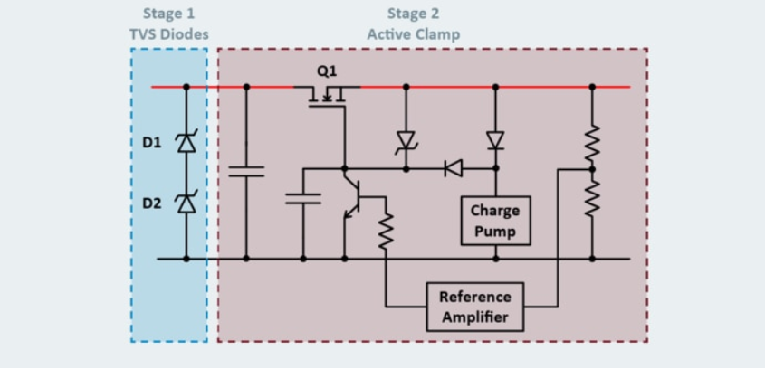
Figure 6: Example of a two-stage transient suppression circuit consisting of a TVS diode stage and an active clamp stage
The second stage of the transient suppression circuitry accommodates long lasting surges. A series FET acts as a linear voltage regulator, actively clamping the module's input voltage within an acceptable range. The selection of this EFT also depends on the input voltage range of the module.
If you want to completely turn off the FET, select a FET rated to withstand the peak voltage of the surge voltage. You should also choose an ON rating that will carry the module's maximum input current during normal operation. The FET draws an input current corresponding to the maximum load current, so R DS(ON) should be as low as possible to minimize power loss.
Finally, the safe operating area (SOA) and transient thermal resistance are determined and evaluated for the clamp conditions when the FET operates.
Summary
Now that the system is built and the protection circuit is complete, the next consideration is the load that the DC-DC module will power.
In the next tutorial, I'll explain what you should be especially careful about with load.