- Semiconductor BusinessHOME
- Products and Services of Macnica,Inc.
-
technical information

-
Events and Seminars
- Handling Manufacturer
- Support
- Inquiry
- Click here to purchase products
- Semiconductor business e-mail magazine registration
![]()
![]() Narrow down by specifying conditions
Narrow down by specifying conditions
現在2186件がヒットしています。check

Advantages of combining modules
DC-DC power modules improve the overall system design process and offer three main advantages.
High performance–
In today's power systems with demanding load requirements, efficient and reliable delivery of power is paramount, and DC-DC modules are a proven solution that makes this possible. Various classes of DC-DC modules are available and offer many advantages in terms of power density, integration and efficiency.
The essence of combining modules–
Modular designs differ from discrete designs in that flexible building blocks can be used to construct complex power systems. For example, you can easily take advantage of advanced power delivery architectures for distributed power systems, such as Vicor's Factorized Power Architecture™ and traditional intermediate bus architectures.
Once developed, it can be easily extended to accommodate different requirements and different power levels. In addition, changes in operational requirements that occur late in the system design process do not completely derail the plan. This is because it can be replaced with another module or increased as system requirements change.
Speed–
Designing with a power module reduces development time from design conception to final implementation while minimizing technical risk.
4 design stages
Stage 1: Basic system requirements
The first step in power system design is to identify system requirements.
Consider the system and its operation by looking at the following questions.
・Where will the electricity be supplied from?
• What are the characteristics of the power source?
• What type of load are you powering?
• Which architecture is most suitable for the requirements of the system?
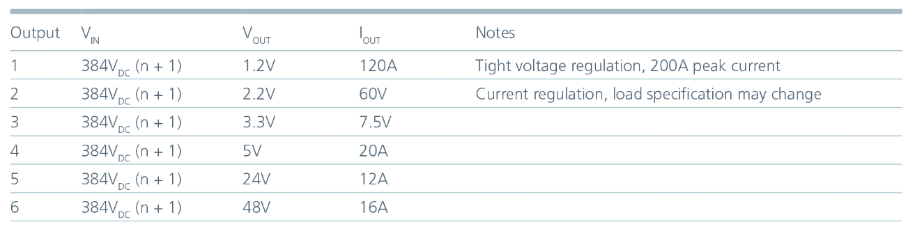
Next, tabulate the system's operating voltage, current, and power levels. List the loads and list the required output voltage and load current requirements.
It's also a good idea to think about when you need special functionality.
In the example below, we have a 1.2V load that requires 120A of current. Its loads have tight regulation requirements and draw peak currents up to 200A. A second example is a 2.2V load (e.g. an LED driver), whose current needs to be controlled.
Stage 2: System architecture
Review the power delivery architecture, select and finalize the required power modules. Create a block diagram of your power system and determine your power delivery architecture, from power source to load. First, list the output of your system (far right in Figure 1). The maximum load is 48V, 16A. A survey of commercially available power modules can help determine which class of module is suitable for supplying the load.
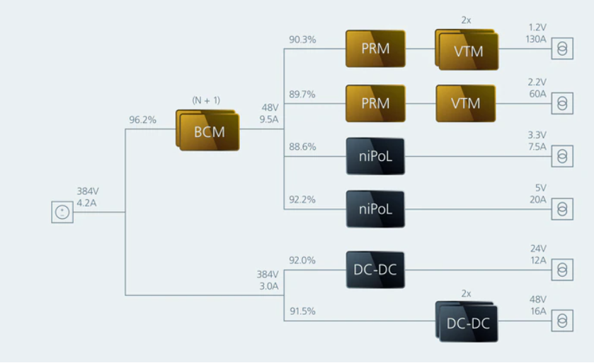
Basic architecture of power system using load and estimated efficiency to check module requirements
Next, consider the physical constraints of your system. Consider the space available for implementation, the design to meet isolation requirements, and the availability of special power delivery network (PDN) architectures. This example shows factorized power (an architecture originated by Vicor) using a 48V bus to feed PoL.
Once the load has been placed and the PoL regulator and power supply modules have been positioned, it is possible to work backwards from the load side to the power source. Using the estimated efficiency from the datasheet of the converter powering each load, calculate the output current requirement for the previous converter. Looking from PoL to the 48V bus, we see that the bus converter must provide at least 9.5A of current, effectively dictating the criteria for choosing a power module.
This design may require adjustments. For example, a 2.2V load could change the load specification and double the current required. This can be easily solved with a modular design approach. Just two voltage conversion modules to meet new design requirements. For the overall system design, adjust the efficiency estimates and load requirements of the preceding bus converter as needed.
Stage 3: Implementation
The module configuration and external circuitry required for final system integration are established in this process. A single module or group of modules is not a complete power system in itself. Various challenges must be addressed in connecting the power source to the load.
Requires additional filtering to comply with EMI standards
・Module protection functions are narrow in scope and often limited to the module itself
・Decoupling is required depending on the characteristics of the power source and load
・Special loads and redundant configurations for high reliability applications
・Connection of system controller and power supply startup sequence
Once the above challenges have been addressed, the majority of the design work is done. We begin by considering an ideal example of a peripheral circuit. Peripheral circuitry is shown around a single DC-DC module for simplicity.
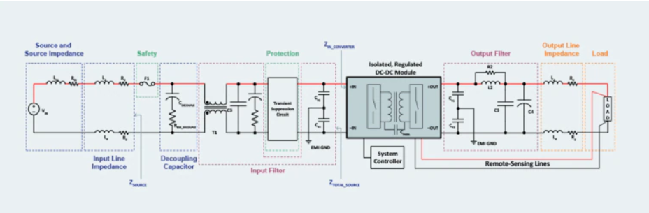
Examples of peripheral circuits required to build a complete system using DC-DC power modules
When working outward from the power module, the input and output must first be filtered to attenuate the noise characteristics of the switching converter.
Next, to ensure system stability, analyze the impedance of the power source and distribution line, and properly decouple the power module (regulator) from the power source. Depending on the operating environment, additional circuitry may be required to protect the system from surges and spikes to meet safety requirements.
Finally, consider how to address any special load concerns.
Stage 4: Module control and monitoring
The final stage of the design process is to lay out the modules and coordinate the interfaces for movement and control/monitor. The power module features various signal and low voltage I/O, including analog and digital interfaces for operating the module.
The analog interface of a typical power module has various control functions. For example, output voltage trimming. In some cases, there is also an enable pin that can be connected to an external controller, and basic monitoring functionality with a fault flag pin. In some cases, the internal temperature is monitored and a voltage corresponding to the temperature is output. Many power modules support PMBus®, a digital interface, for monitoring and control, including output voltage trimming, enable/disable control, and more.
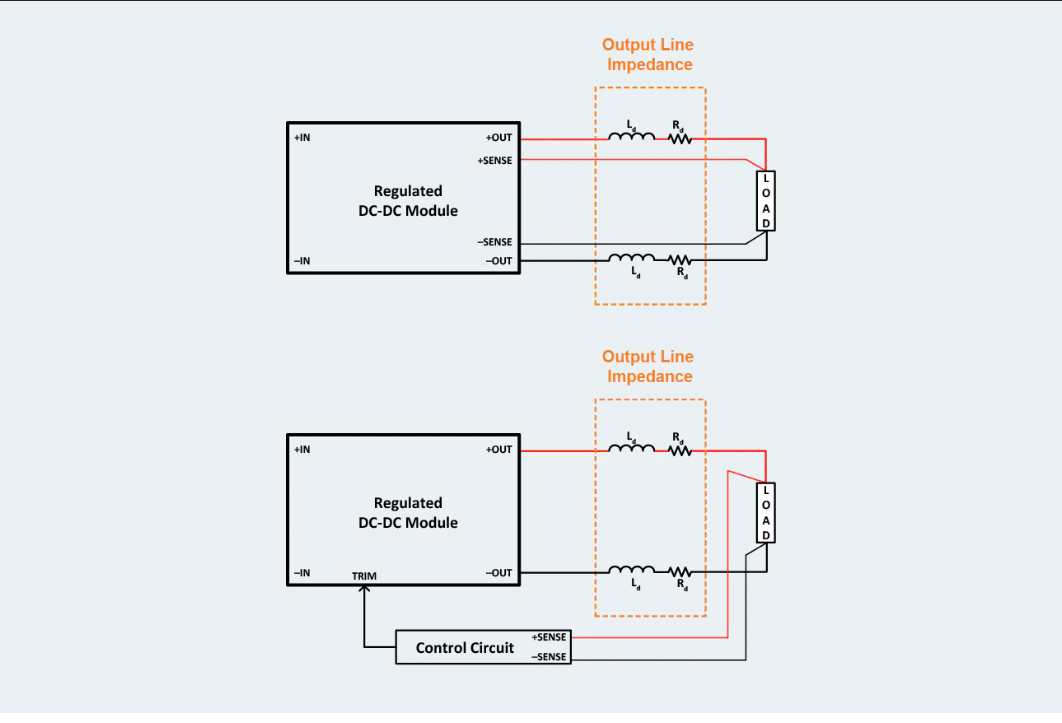
Current limit thresholds and fault protection may be configurable, allowing the module's behavior to be tailored to the needs of the application. In addition, some have excellent ability to identify the cause of faults, such as undervoltage, overvoltage, and overcurrent events, by flagging fault conditions. Regulator-type modules often have remote sensing capabilities that allow them to accurately regulate voltage at the point of load by compensating for voltage drops due to distribution line impedance.
By Kelvin-connecting two sense wires to the load terminals, remote sensing can directly monitor the voltage at the load, thus canceling out the voltage drop that occurs in high-current distribution systems.
Analog and digital control signals with power modules
For either analog or digital control signals, it is important to separate the power circuit ground and the ground for low power control signals. If a low-power signal shares the same ground return path as the module's power output, high-frequency noise generated by the module's switching activity can be coupled into the control signal by parasitics, resulting in erratic operation. there is. Connect the signal and power grounds at only one point so that no power current flows through the signal ground.
Summary
This article provided a general overview of system design using DC-DC power modules.
Subsequent tutorial series will explore the main considerations of the third stage of the design in more detail.