- Semiconductor BusinessHOME
- Products and Services of Macnica,Inc.
-
technical information

-
Events and Seminars
- Handling Manufacturer
- Support
- Inquiry
- Click here to purchase products
- Semiconductor business e-mail magazine registration
![]()
![]() Narrow down by specifying conditions
Narrow down by specifying conditions
現在2189件がヒットしています。check
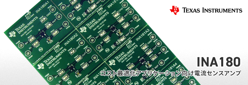
The other day, I introduced current sense amplifiers in an article titled "Mechanisms of current sense amplifiers that achieve high-precision current detection and their advantages and disadvantages." This time, I will introduce a current sense amplifier called INA180 from Texas Instruments (hereafter TI).
Features of the compact current sense amplifier INA180
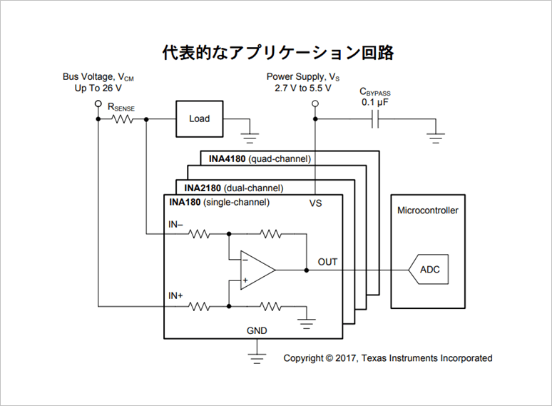
The INA180 is an analog voltage output type compact current sense amplifier developed for cost sensitive applications. The main features are as follows.
1.Common mode voltage range
The INA180 supports a common mode voltage range of -0.2 to 26V independent of the supply voltage (2.7 to 5.5V).
2. Built-in matched fixed-gain resistor network
Four fixed gain devices (20V/V, 50V/V, 100V/V, 200V/V) are available. The gain error is ±1% (maximum) and the offset drift coefficient is 1uV/°C (maximum) under the temperature range of -40°C to 125°C.
3.Single, dual, and quad products are available according to the application.
INA180 (single product), INA2180 (dual product), and INA4180 (quad product) are available. Current consumption is 260uA for INA180, 500uA for INA2180, and 900uA for INA4180.
Evaluation kit for immediate evaluation
INA180-181EVM
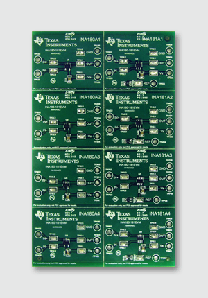
The INA180-181EVM is an evaluation module for basic functional evaluation of this device family.
Although it consists of one PCB, this PCB can be separated into 8 individual PCBs to mount each of the 8 different devices (INA180A1, INA180A2, INA180A3, INA180A4, INA181A1, INA181A2, INA181A3, INA181A4). increase.
*Accessory layouts are not intended to be used for modeling target circuits or for electromagnetic compatibility (EMC) testing.
Features
- Evaluate all INA180Ax and INA181Ax gain options
- Easy access to device pins with multiple test points
- Both high-side and low-side configurations can be evaluated
Application example
- motor control
- battery monitoring
- Power Management
- lighting control
- Overcurrent detection
- solar inverter

Recommended reference designs
<90mW Ultra-Low Standby Power, Auxiliary-Free AC/DC Power Supply Reference Design
http://www.tij.co.jp/tool/jp/PMP21251
High Efficiency, Low Total Harmonic Distortion (THD), 200W AC/DC LED Driver Reference Design
http://www.tij.co.jp/tool/jp/PMP20612
Product Summary
| Type name | THVD1550D |
| specification |
|
Click here for recommended articles/materials
Mechanism, advantages, and disadvantages of a current sense amplifier that achieves high-precision current detection
Three features of zero-drift nanopower operational amplifiers
4 Reference Designs Specializing in Preventive Maintenance of Motors and Plungers
Is capacitive isolation better than optocouplers?
Click here for product price information and availability
Click here for manufacturer site/other related links
Inquiry

