- Semiconductor BusinessHOME
- Products and Services of Macnica,Inc.
-
technical information

-
Events and Seminars
- Handling Manufacturer
- Support
- Inquiry
- Click here to purchase products
- Semiconductor business e-mail magazine registration
![]()
![]() Narrow down by specifying conditions
Narrow down by specifying conditions
現在2168件がヒットしています。check

A digital isolator is required for a safe design
There are many cases where insulation is required not only for applications that handle high voltage, such as industrial equipment and medical equipment, but also for various applications. In order to prevent noise injection, etc., an isolator product that is electrically insulated (a barrier that blocks common-mode voltage) is required.
In this article, we will discuss capacitive isolation among the three common isolation methods.
General insulation method
First, let's briefly touch on common isolation methods. In the past, the most widely used electrical isolation method was signal isolation using a photocoupler, but in recent years semiconductor vendors have released new isolation elements. Each method is briefly described below.
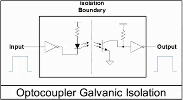
Optical isolation
A light-emitting element and a light-receiving element are molded into a single package, and the voltage signal input to the photocoupler is converted into an optical signal by these internal elements, allowing the signal to be passed from the light-emitting side to the light-receiving side while ensuring insulation. can. It is the oldest of the three methods and is easy to use, but it is generally characterized by low speed and large power consumption, and is said to deteriorate faster over time than the other methods.
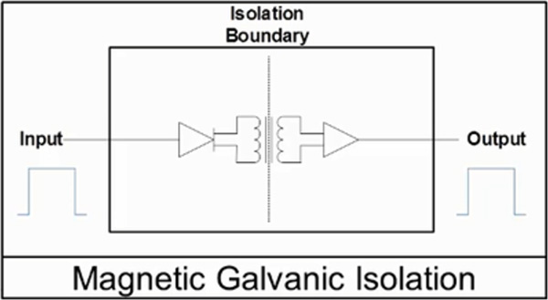
Inductive (magnetic coupling, inductive) isolation
In this method, coils made by a semiconductor process are used on the primary and secondary sides, and signals are passed between these insulated coils.
*Even in the same magnetic coupling, there is also a method that uses GMR (magnetic resistance).
The advantage of this method is that although the life is longer than that of optocouplers, the current consumption increases with the data speed, and the magnetic isolation is said to be susceptible to electromagnetic interference. Also, unlike optocouplers, this method does not support analog signals. However, there are isolation amplifiers that can handle analog signals as well.
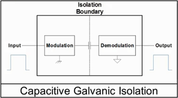
Capacitive isolation
Capacitive isolation uses SiO2 Capacitor to achieve (double) isolation on the input side and the output side, and, like magnetic isolation, it is a method of passing AC signals between these insulated capacitors. This isolation method has a longer life than optocouplers, maintains high data speeds, keeps current consumption low, and is less susceptible to magnetic noise.
Also, like inductive isolation, this method does not support analog signals, but there are isolation amplifiers that can handle analog signals as well.
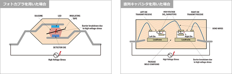
SiO2 has a very high breakdown threshold (withstand voltage)
SiO2 has a much higher breakdown threshold (withstand voltage) of ~800V/um compared to ~50V/um for the mold compound that optocouplers use for isolation. This makes it possible to handle temporary overvoltages, surge voltages, or voltages that are continuously applied over several years.
There are three reasons for having this high destruction threshold:
Enhanced isolation with series capacitor configuration
For reinforced isolation against high voltage, each channel uses isolation capacitors on both dies, which are connected in series.
High voltage stress with isolator
The thickness of the isolated capacitor is 21um or more (SiO2)
Each capacitor is formed of SiO2 capacitors over approximately 10.5um thick, and the isolation capacitors combined in series are over 21um thick.
Galvanic barrier provides excellent EM immunity and excellent isolation barrier life
The series-connected capacitor structure provides high isolation capability, with a surge voltage rating greater than 12.8kV, a peak transient overvoltage of 8kV, and a working voltage of 1.5Vrms.
Advantages of capacitive isolation over optocouplers
ここで、具体的にフォトカプラに対する優位点をいくつか挙げます。
Benefits of using digital isolators with capacitive isolation
- Low deterioration over time and long service life
- High breakdown field value
- High Common Mode Transient Voltage (CMTI)
- Because the propagation delay time is short,
- Wide operating temperature range
- The structure of the insulation part is a two-chip structure, so even if it is destroyed, the possibility of shorting the input and output is low.
Comparison of capacitive isolation (TI product) and photocoupler
| Capacitive isolation (TI ISO78xx) | Photo coupler | |
| Method | Capacitor | Opt |
| Absolute Rating (UL, 20% margin) | 5.7k Vrms | 5 kVrms |
| Reinforced insulation (10kV surge) | ✓(12.8kV) | ✓ |
| Insulation working voltage (Bipolar AC, 25yr) |
1500 Vrms | 870 Vrms |
| Withstand voltage | 800V/um | 50V/um |
| Common Mode Transient Voltage (CMTI) | 100kV/us | >25kV/us |
| Tracking resistance (CTI) | >600V | > 175V |
| delay time | 16ns | 100ns |
| Operating temperature range | -55 to 125℃ | -40 to 85℃/105℃ |
If the structure of the insulation part is a two-chip configuration, one capacitor can be expected to maintain insulation even after a high-power event occurs.
In "6" above, we mentioned the advantage of the two-chip configuration, but under abnormal events, one side of the isolator may be subjected to high voltage and high current relative to ground. This can, for example, cause a short circuit when an output pin has a low impedance, or a pin connected to a high voltage bus line can short circuit and cause electrical breakdown. These are high power events where high voltage and high current are present at the same time.
When these events occur, electrical overstress and internal heat can degrade the insulation barrier.
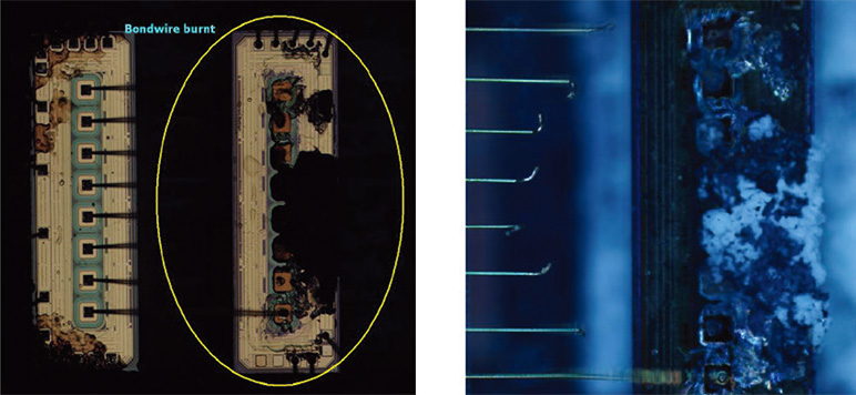
For photocoupler
High power events on one side cause heat and EOS on the detector die. This damage results in degradation of insulation performance, after which it is difficult to quantify how much dielectric strength remains.
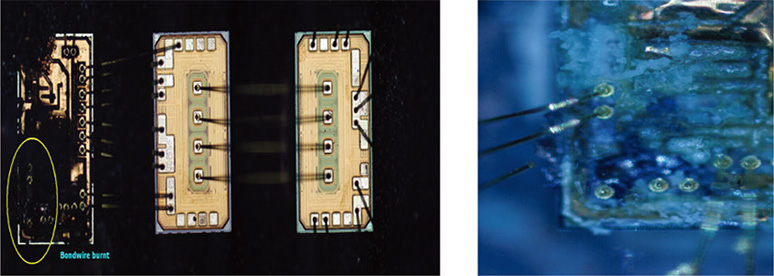
For capacitive isolation connected in series
A high voltage/high power event on one side can also damage the die, but the mold compound contained in between prevents further damage to the other die and the capacitors, providing true isolation. About half of the performance can be maintained.
This means that, for example, if the original isolator had reinforced insulation, isolation can be expected with a single capacitor even after a high-power event occurs, and at least "basic insulation" is expected to be maintained. can. (See diagram below)
EOS damage remains only on die receiving high power (ISO7841)
EOS damage is confined only to the driver die receiving high power (ISO5851)
Digital isolator from Texas Instruments
TI社のデジタル・アイソレータ代表製品は以下の2種類があります。
- ISO7842 (4ch Robust Reinforced ISO)
- ISO7821 (2ch Robust Reinforced ISO)
For more information, please visit the pages below or contact us.
Texas Instruments ISO78xx Digital Isolators (Macnica-Mouser Page)
Related services/links
Related services
Click here for recommended articles/materials
Isolated IGBT gate driver ISO5452 with capacitive isolation
Why does DDR memory need a dedicated power supply?
WEBENCH® is overwhelmingly easy to use! Engineers talk about 5 attractions
When is the simulation function of WEBENCH® Power Designer useful?
Click here to purchase products
Click here for manufacturer site/other related links
Understanding Failure Modes in Isolators
TI Precision Labs – Isolation (Video)
How High-Voltage Isolation Technology Works (Video)
Next generation digital isolation (video)
Contact Us

