- Semiconductor BusinessHOME
- Products and Services of Macnica,Inc.
-
technical information

-
Events and Seminars
- Handling Manufacturer
- Support
- Inquiry
- Click here to purchase products
- Semiconductor business e-mail magazine registration
![]()
![]() Narrow down by specifying conditions
Narrow down by specifying conditions
現在2171件がヒットしています。check
In the past, when a machine broke down at a factory or manufacturing site, people rushed to the spot after the breakdown and used human senses to detect anomalies. Also, the only way to prevent failures was to spend money on maintenance/maintenance. As factory automation progresses, there is a growing need to automate this anomaly detection by a system and predict the occurrence of failures.
This time, we will introduce the contents of a demonstration video that detects defects in equipment such as motors and pumps using Texas Instruments (hereafter TI) processors. We will also explain how to actually automate anomaly detection and the benefits of using TI's reference design.
Vibration monitoring demonstration using TI's high-precision ADC built-in processor
*To watch with English subtitles, click the CC mark at the bottom of the video and select English.
Video flow
0:00 - 1:29 Overview and demo environment introduction
- Enables early detection of defects in rotating parts of motors and pumps, misalignment of shafts, and defects in motor installation
- The reference design used consists of a high-precision ADC built-in processor, a Bluetooth microcomputer, and an accelerometer.
- The motor used is a brushless DC motor (3,600RPM/60cps), and the motor and torque are connected by a shaft.
1:29 - 2:24 Setup
- Check the output of the 3-axis accelerometer on the horizontal axis: time on the oscilloscope
- Check the vibration peak frequency on the horizontal axis: frequency in the TI app
- In the frequency distribution, confirm that the peak frequency on the x, y, and z axes is concentrated at 60 Hz, and confirm the 5th harmonic on the x and z axes
2:24 - 3:01 Explanation of Demo #1 ~ Shaft Misalignment ~
- The sound of the noise changed, and it was confirmed from the video that the shaft was shaking.
- Check that the x, y, and z axis peaks are distributed at separate frequencies in the frequency distribution
3:01 - 4:02 Explanation of Demo #2 ~Loosen the motor mounting bolt half a turn~
- Confirm that the shaft is shaking in the slow video
- For each frequency distribution, it is confirmed that the frequency of vibration is widely distributed on all of the x, y, and z axes.
Points to keep in mind
Abnormalities can be detected from vibration frequency data
By comparing the x-, y-, and z-axis components based on the normal frequency data, it is possible to detect waveforms that differ from normal and detect abnormalities.
Easy acquisition of vibration data that can be used for anomaly detection
Data can be acquired from outside the equipment without stopping equipment such as motors and pumps, making introduction smoother.
There is already design data and applications for reference designs without starting from scratch
The reference design used in the demonstration has all the circuit diagrams and layouts necessary for designing. A demo application is also available for one-stop preparation, including waveform analysis. It is ideal for those who want to try how vibration monitoring can be realized first.

TI reference design used in demo video
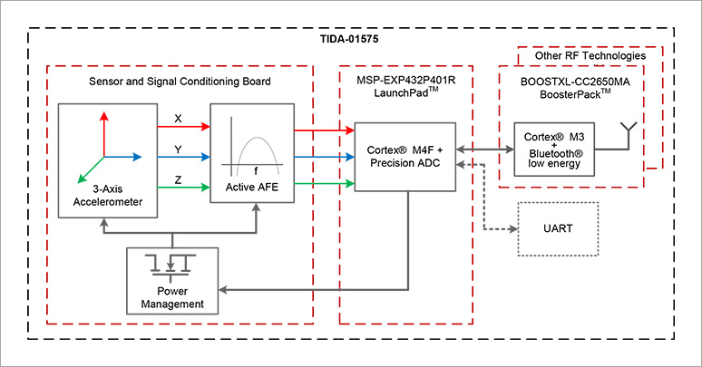
TIDA-01575
TIDA-01575 is a reference design for predictive maintenance that allows non-disruptive, external monitoring of equipment such as motors and pumps. It consists of three boards, and the data acquired by the 3-axis acceleration sensor is processed by a high-precision ADC built-in processor, and the data is transferred from the Bluetooth wireless microcomputer to a smartphone, etc.
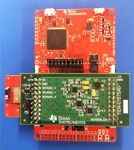
Composition of TIDA-01575
- MSP-EXP432P401R LaunchPad
- BOOSTXL-CC2650MA Booster Pack
- 3-axis accelerometer/signal conditioning
This reference design TIDA-01575 is not sold by TI or Macnica-Mouser, and the design data is open to the public. The configuration boards, MSP-EXP432P401R LaunchPad and BOOSTXL-CC2650MA Booster Pack, are available for purchase.
MSP-EXP432P401R LaunchPad
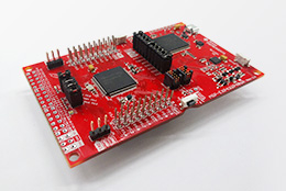
This board adopts a 32-bit Arm® Cortex® -M4F core and inherits the features of the MSP430 microcontroller series, and is a high-performance, low-power MSP432 microcontroller evaluation board.
BOOSTXL-CC2650MA
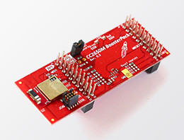
The BOOSTXL-CC2650MA Booster Pack is a quick and easy way to add Bluetooth low energy to any LaunchPad™ development kit.
For more information, please contact us
By predicting the service life of devices such as motors based on vibration data, we hope you will find it useful in resolving issues such as maintenance costs that you have faced up until now.


Click here for recommended articles/materials
Motor control using a microcomputer -Brushless DC motor control explained with video-
Trying to operate a brushless DC motor and encoder with Sitara™ AM437x
LAUNCHXL-F28027F realizes sensorless motor control in just 5 minutes
Click here to purchase products
Click here for manufacturer site/other related links
TIDA-01575 product page
MSP-EXP432P401R LaunchPad product page
BOOSTXL-CC2650MA Booster Pack Product Page