
![]()
![]() Narrow down by specifying conditions
Narrow down by specifying conditions
現在2003件がヒットしています。check
Introduction
This time, sensing is performed with ONSEMI's RSL10.
Here, we will guide those who are developing the RSL10 for the first time and those who will be developing it for the first time on how to perform sensing with the RSL10. This article is the second part of a two-part structure.
Please refer to the following for the first part of the article on sensing with RSL10.
Bluetooth®5 certified SoC, RSL10 first time evaluation all 3 times record"-Part 2 Part 1"Sensing"error occurred with RSL10"
About the summary of the first part article and the contents of this second part article
Last time I downloaded the sample code and built it.
I debugged using the noa1305_example.elf file created after building.
However, I got an error message.
In this article, I will explain the flow of finding the cause of the error and how to actually execute sensing with RSL10.
How to identify the cause of the error and how to perform sensing
1. First, I checked to see if there was a problem with the hardware.
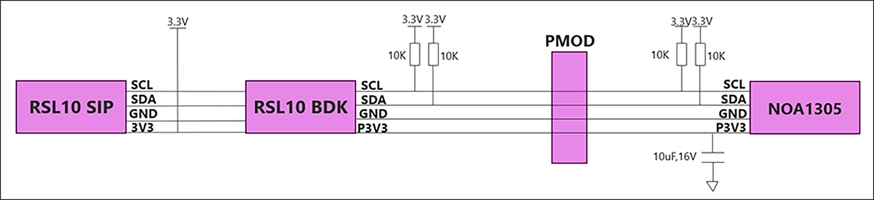
We have confirmed that there is no problem with the connection between the sensor part and RSL10-BDK-GEVK (described as RSL10 BDK on the connection diagram) and RSL10-SIP-001GEVB (described as RSL10 SIP on the connection diagram).
A connection diagram is shown in Figure 1 below.
It turned out that there was no problem with the hardware connection.
2. Next, I checked for software problems.
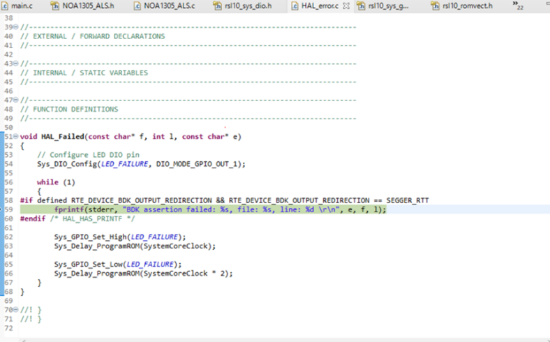
You can see the following error code when debugging. Shown in Figure 2.
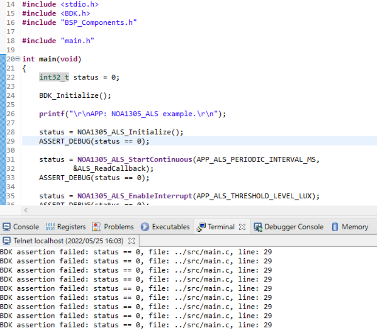
From Figure 2, you can see that an error occurred on line 29 of the main.c file and it is not working. Therefore, I decided to find the cause of the error by executing it line by line during debugging.
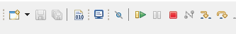
In the past, after clicking Debug, I clicked Resume (F8), but I will find out by executing the program line by line at the rightmost Step Over in Figure 3 below.
I will explain STEP Over.
STEP Over: Go to the next paused line and pause. If a method is called in the target line, perform those processes and proceed to the next line.
This time, an error occurs on line 29, so step over to line 24. Execute Step Into after executing Step Over.
Explain STEP Into.
Step Into: Go to the next paused line and pause. If the target line calls a method, enter the called method and pause at the beginning.
Dive into Step Into and you'll see that it loops: (See Fig. 4)
Therefore, it can be assumed that there is a problem with the DIO connection.
3. So I checked the connection destination of DIO of RSL10-SIP-001GEVB and RSL10-BDK-GEVK.
Figure 5 summarizes where the DIOs of the RSL10-SIP-001BEVB and RSL10-BDK-GEVK connect.
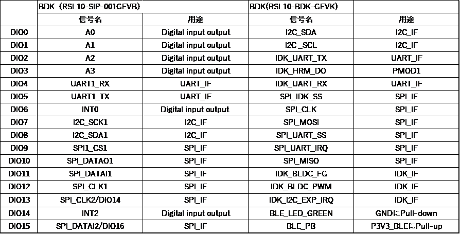
If you check the connection destination of DIO, you can see that the connection destination of RSL10-SIP-001BEVB and RSL10-BDK-GEVK are not the same. Also, the downloaded sample code corresponds to RSL10-BDK-GEVK. In other words, the sample code is defined with DIOs for RSL10-BDK-GEVK, so we need to define the corresponding DIOs for RSL10-SIP-001BEVB.
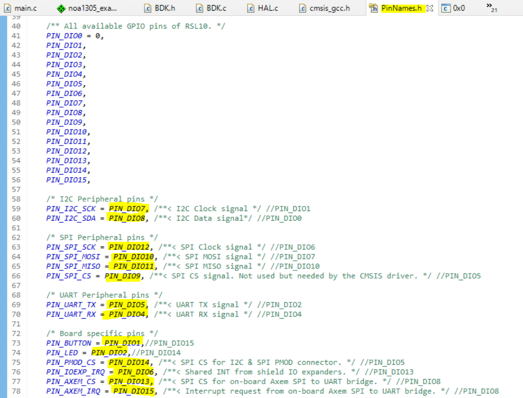
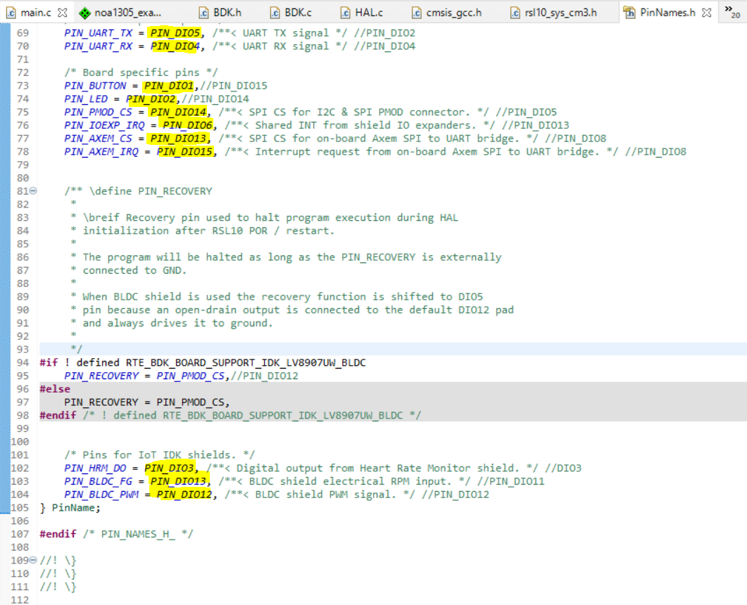
4. Define DIO corresponding to RSL10-SIP-001BEVB.
Inside the PinName.h file, rewrite the following PIN_DIO lined in yellow and save it. (See Figure 6)
5. Right-click the folder for NOA1305_example and click Build Project again. Alternatively, select a project and click [Build Project].
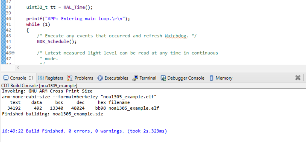
6. Once the build is executed, the output of the build will be displayed on the on-semi IDE C/C++ as shown in Figure 7.
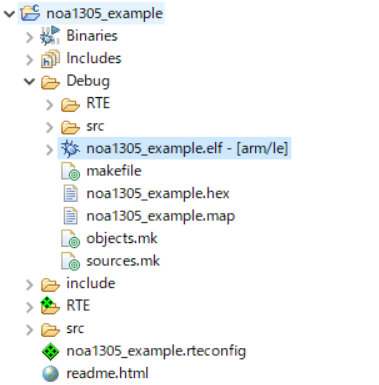
7. The main results output to the Debug folder on the Project Explorer are as follows. Shown in Figure 8.
The file used for sensing is noa1305_example.elf.
8. Debug using the noa1305_example.elf file. Right-click the noa1305_example.elf file in the Project Explorer and select Debug As > Debug Configurations.
9. When the Debug Configurations dialog appears, right-click GDB SEGGER J-Link Debugging and select New Configuration.
You will see a new configuration of noa1305_example.elf under the GDB SEGGER heading.
The details of the new configuration appear in the right panel.
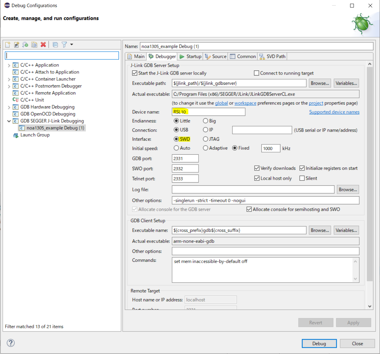
10. Go to the Debugger tab and enter "RSL10" in the "Device Name" field.
Make sure SWD is selected as the target interface. (See Fig. 9)
11. After the configuration update is complete, connect the evaluation and development board to your PC with a micro USB cable and click Debug.
J-Link will automatically download the noa1305_example example code and save it to the RSL10 's flash memory.
12. After clicking Debug, click Resume (F8) in Figure 10 below.

13. After clicking Resume, click Open a terminal in Figure 11 below.

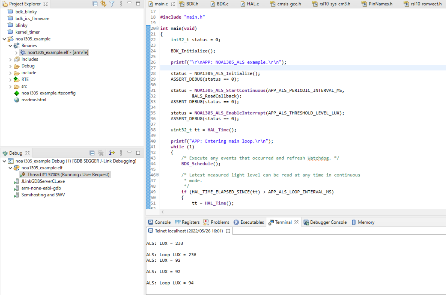
14. I was able to confirm the operation. (See Figure 12)
At the end
This time, I used ONSEMI's RSL10 for sensing. Next time (3rd), I would like to build a demo environment using BLE communication with RSL10.
Inquiry
If you are interested in the contents and products introduced this time, please contact us.
Onsemi Manufacturer information Top
If you want to go back to ONSEMI Manufacturer Information Top, please click below.