- Semiconductor BusinessHOME
- Products and Services of Macnica,Inc.
-
technical information

-
Events and Seminars
- Handling Manufacturer
- Support
- Inquiry
- Click here to purchase products
- Semiconductor business e-mail magazine registration
![]()
![]() Narrow down by specifying conditions
Narrow down by specifying conditions
現在2191件がヒットしています。check

closed loop gain
We mentioned earlier that a PLL has a steady-state phase error, but the steady-state phase error varies with the closed-loop total gain of the PLL. A PLL consists of a negative feedback circuit as shown by the blue line. The total gain is the multiplication of each block's gain.
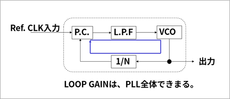
PC: Gain that changes the phase comparison information to a voltage value
LPF: gain of op amp for active Filter
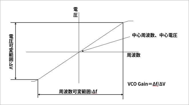
VCO: Voltage/frequency conversion efficiency (Δf/voltage variable range)
1/N Divider: Gain is 1/N compared to using Reference Clock
This total gain has a lot to do with the steady-state phase error of the PLL. If the total gain is high, the phase error will be small, and if it is low, the phase error will be large. Also, since Total Gain amplifies the jitter that is superimposed on the reference clock, we must also consider the characteristics of the high-order LPF to see how much jitter can be suppressed. It is necessary to consider Gain, Filter Cut Off, etc. depending on which element is emphasized for the system specifications.
Inquiry
If you have any questions regarding this article, please contact us below.
To Microchip manufacturer information Top
If you want to return to Microchip manufacturer information top page, please click below.