- Semiconductor BusinessHOME
- Products and Services of Macnica,Inc.
-
technical information

-
Events and Seminars
- Handling Manufacturer
- Support
- Inquiry
- Click here to purchase products
- Semiconductor business e-mail magazine registration
![]()
![]() Narrow down by specifying conditions
Narrow down by specifying conditions
現在2189件がヒットしています。check

Introduction
Long time no see. I'm Topu, who was in charge of the "Blush Blog" in 2015.
Now, as a third-year employee, I am working hard to provide support.
Well, this time I would like to introduce a tool I used called HyperLynx®. Let's get started.
One day, I came across the following YouTube video of IBIS model generation from the Intel® PSG (formerly Altera) email newsletter (Monthly News Update).
<IBIS model generation>
https://www.youtube.com/watch?v=izcVsZGu2Ws
This video shows you how to generate IBIS files in Quartus® II (Quartus Prime). When I followed this procedure, an IBIS file was indeed generated.
However, there is no further introduction! I was at a loss as to how to use it, so I asked a senior colleague, and he answered, "HyperLynx!" So I actually tried it.
I made an IBIS file
First, I created an IBIS file using Quartus. In the video, Quartus II was used, but I will of course be using the latest version, Quartus Prime ver16.1.
Select Cyclone® V as the device, turn on the setting to generate an IBIS file, and run a full compilation. This time I tried using the DDR3 controller IP Example Design.
Please watch the video above for detailed instructions on how to create it. (Just under 7 minutes)
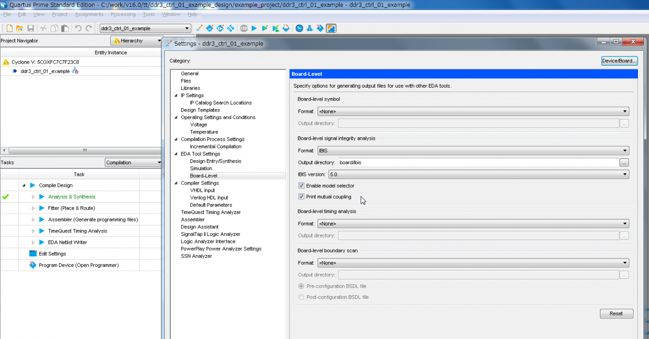
When the full compilation is finished and you look at the project folder, you will see a board folder. And in this...
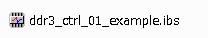
there was! A file called ddr3_ctrl_01_example.ibs has been created. This is an IBIS file. The file name is generated with the name of the project.
Now that we have an IBIS file, we can finally use HyperLynx. HyperLynx is already installed.
Oops, before that. . .
What is HyperLynx?
HyperLynx is MentorGraphics' board verification tool. You can perform signal quality of printed circuit board transmission lines and power plane analysis. Problems in board design can be discovered early.
⇒ Click here for details
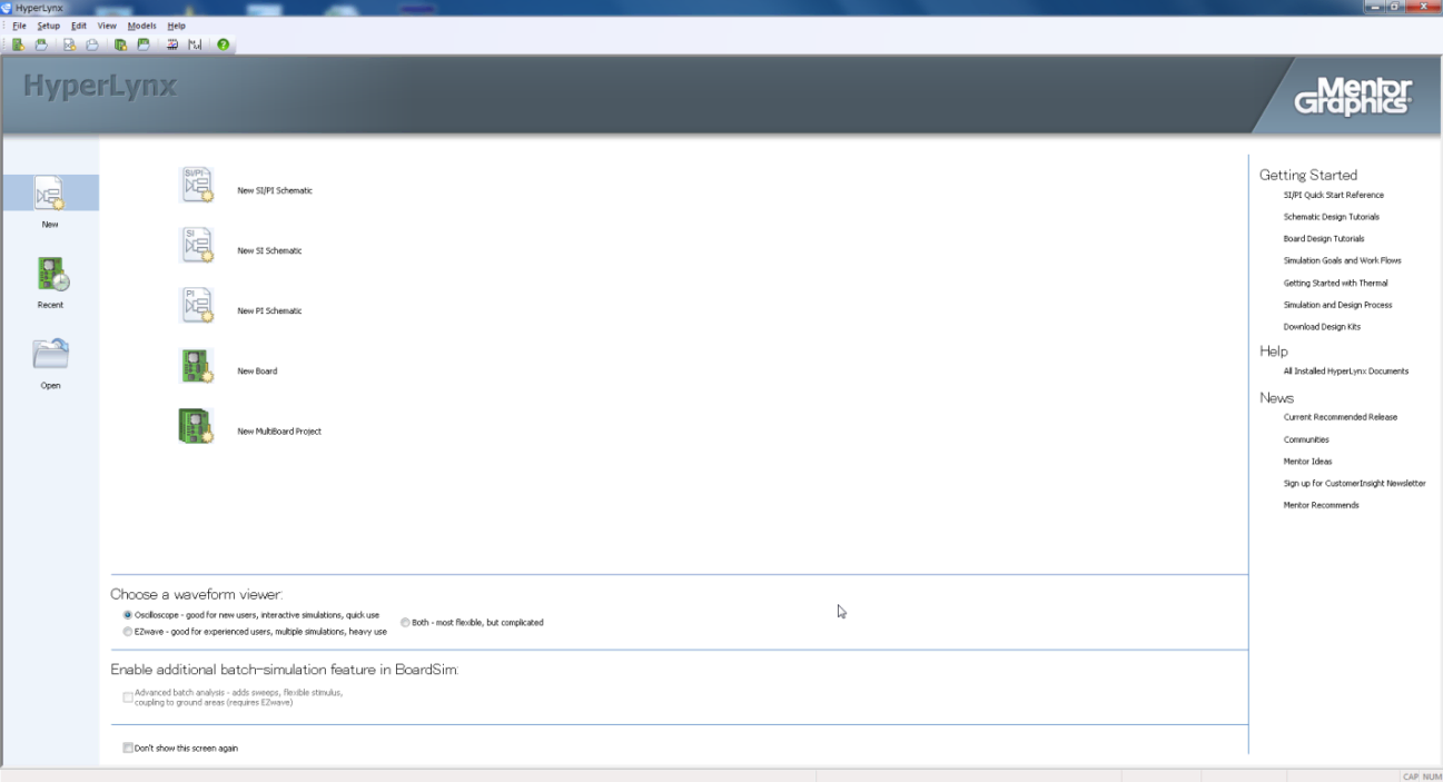
Start HyperLynx
Start HyperLynx SI/PI. (There are more than SI/PI in the HyperLynx series, but I will introduce them on another occasion.)
When you start it, a screen like the one shown below (Fig. 2) will appear. This time, click New SI Schematic in this.
Then, an empty sheet started up (Fig. 3).
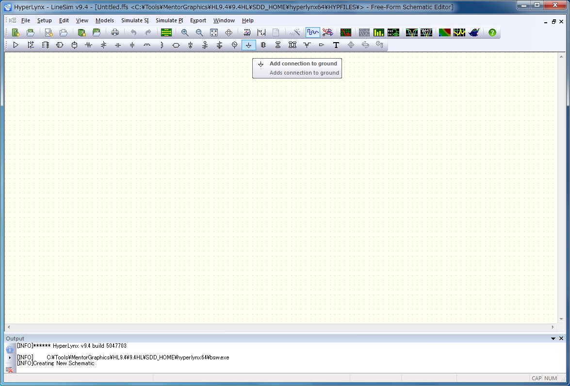
This is the sheet used in HyperLynx SI's LineSim. LineSim is called pre-simulation or pre-analysis, and it creates the topology of the transmission line between devices on a sheet and performs a transmission line simulation.
This pre-simulation is an analysis before determining the board layout and wiring, and allows you to check the validity of the topology.
Create a topology
Let's create a topology on the sheet.
Oops, before that, we should set the layer structure of the board. For this example, we will use the default settings.
By the way, the layer configuration is set from the Stackup Editor. By default, the settings are for a 6-layer board as shown below (Fig. 4).
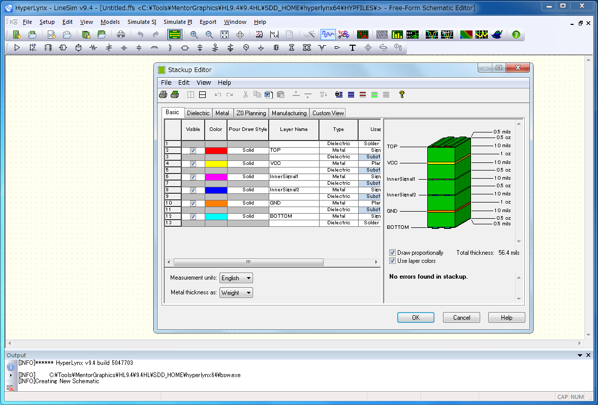
Close the Stackup Editor window and create the topology.
Let's simulate the address signal transmission path between Cyclone V and DDR3.
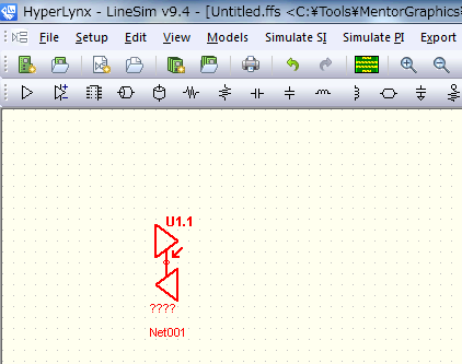
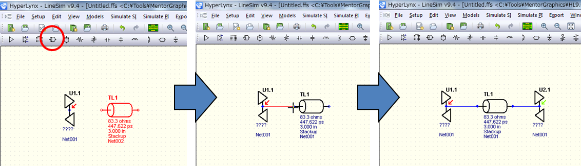
First, add the driver. The leftmost icon in the menu bar below at the top of the sheet is the IC pin.

Click this icon and click again on the desired location on the sheet to place the IC pin as shown below (Fig. 6).
Next, add a transmission path. The transmission path is the fourth icon from the left. After placing the transmission line, connect it to the driver's IC pin.
Finally, place one more IC pin and connect it to the transmission line.
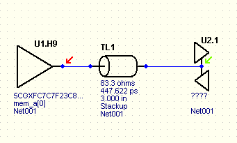
This completes the simplest topology (Figure 7).
Now, there's one more thing we need to do before we start the simulation. It is the IC pin model assignment.
If you look closely at Figure 7, you can see that the driver and receiver IC pins are marked ????. This is because no IC pin model is assigned.
IC pin model assignment
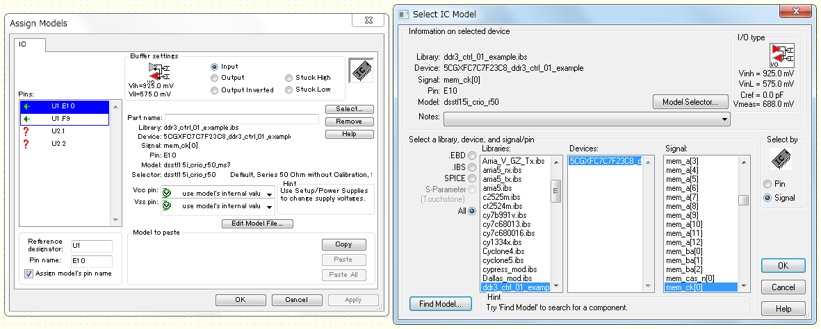
Double-click the driver's IC pin on the schematic. A window called Assign Models will start, so click the Select button to open the Select IC Model window.
Now select the ddr3_ctrl_01_example.ibs you created earlier, and the device model number 5CGXFC7.. will be displayed in Device. Select the pin (model) to simulate in the Signal field. This time, we want to simulate the address pin, so select the mem_a[0] pin (Figure 8).
One point here★
I chose mem_a[0] like this, where mem_a is the pin name in the design. This is one advantage of generating an IBIS file in Quartus.
See next time for details
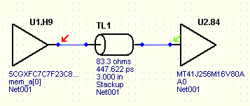
The pin (model) used for simulation was selected from the IBIS model, so the model was assigned to the IC pin on the schematic as shown in Figure 9. .
Set the receiver side in the same way. Now we need to use the IBIS model of DDR. Obtain this from your memory vendor. There are also some that can be downloaded from the web, so please check them out.
When the receiver model settings are completed, it will look like Figure 10. The simulation is now ready.
I would like to run a simulation right away, but that's all for now.
I will try running the simulation next time. looking forward to!