FPGA を使った時計の製作実習中のことです。
I used the Intel® Quartus® Prime software to write counters for seconds, minutes, and hours.
The single-digit second counter (0 to 9) should have been counted up by the clock enable signal, so it worked well,
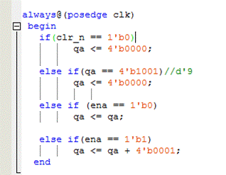
Carrying up to second digits (09 → 10) did not work well. Here is my design from that time.

Even if the first digit of the second passed 9 at the rise of the clock, I could not confirm that the second digit of the second was counting up.
Therefore, I created a circuit that ignores the clock enable signal and counts up the second digit after the first digit of the second is 9, and confirmed it on the actual machine.
The second digit counted 1 when the second digit was 8.
Here is the image of the simulation.

That means
Shouldn't the second digit count up to 10 and then the second digit count up? When I rewrote the circuit thinking of something untoward,
I was able to confirm the carry display on the actual machine.
However, it was difficult to carry from two digits of second to one digit of minute, so when I asked my senior to see the design, he did not understand the if statement at all. One word.
I don't see any errors in the Quartus® II development software, so I wonder what's wrong...
According to my senior, the if statement checks the truth of the conditional statements in order from the top.
Based on that, I will try to translate the previous design into Japanese.

I lost track of what I was writing and what I wanted it to do.
You don't need the last two lines.
It took me a long time because I confused the Quartus® II development software. . . Sorry Quartus® II.
As you can see from the description of the second else if,
The description stated that qa takes data on the “rising edge of clk” in 4'b1001 (9) and sets qa to zero.
It was 9 only at the moment when 1MHz of the clock went High, but it's not really recognizable by human eyes, is it?
In the above description, I found that the conditional branching was going back and forth.
The conditional signal other than clk and clr_n was clk_en. clk_en is a 1s cycle signal generated based on a 1MHz clock.
I just wanted to count up with 1s clk_en as a trigger. I can't describe it unless the priority of the conditional expression is clear.
Here is the description of the improved counter.
always@(posedge clk)
begin
if (clr_n == 1'b0)
qa <= 4'b0000;//d'0
else if (clk_en == 1'b1)
if(qa == 4'b1001)//d'9
qa <= 4'b0000;
else
qa <= qa + 4'b0001;
else
qa <= qa;
end
When using the if statement, it was necessary to prioritize each signal and write the conditional statement from the highest priority.
Excessive nesting complicates the conditions and may create redundant logic unintended by the designer.
It turns out that it consumes a lot of FPGA logic elements (LEs).
As an example, last time I created a clock design with incorrect counters nested too much, it consumed around 700LE.
However, by rewriting the description, the consumption was reduced to about 40LE.
It seems that a concise and optimal description is necessary for effective use of FPGA.
The tool also optimizes, but it has its limits.
We have recognized the importance of a design description in order to maximize the functionality of our tools.
