- Semiconductor BusinessHOME
- Products and Services of Macnica,Inc.
-
technical information

-
Events and Seminars
- Handling Manufacturer
- Support
- Inquiry
- Click here to purchase products
- Semiconductor business e-mail magazine registration
![]()
![]() Narrow down by specifying conditions
Narrow down by specifying conditions
現在2168件がヒットしています。check

We will explain in detail how to use the PowerPlay Early Power Estimator (EPE) external link, which is intended for selecting a power supply for the Cyclone® V SoC (5CSXFC5D).
In the previous column, I introduced how to use EPE in five steps to find the FPGA's power and select a power supply, but this time I will introduce a more specific method of using EPE to check the power supply rail. It will be.
Understand the power supply specifications based on the type of FPGA and prepare pin connection guidelines
- Select FPGA (Devices are narrowed down by accuracy of output voltage)
- Be prepared by opening the target device family page of the pin connection guidelines so that you can quickly check the necessary information.
start design
Now let's start power supply selection using EPE.
Select FPGA usage conditions Part 1
Now let's start power supply selection using EPE.
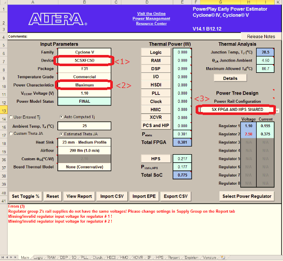
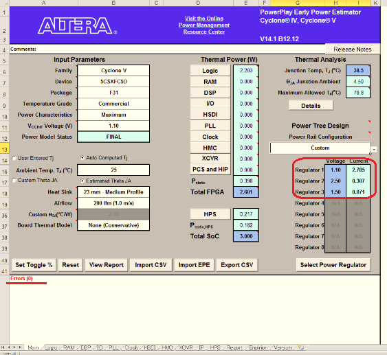
- Select Device on the Main tab. (See image 01 <1>)
- Select Power Charactrization as Maximum. (See image 01 <2>)
- Select Power Rail Configuration in some cases.
- This time I chose SX FPGA and HPS Shared. (See image 01 <3>)
Select FPGA usage conditions Part 2
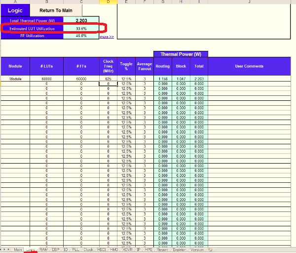
- Enter the required information on each tab. (This time, enter only the Logic tab)
- It is assumed that Look Up Table, FF, and Clock Frequency are used with the selected device fully utilized. (see image 02)
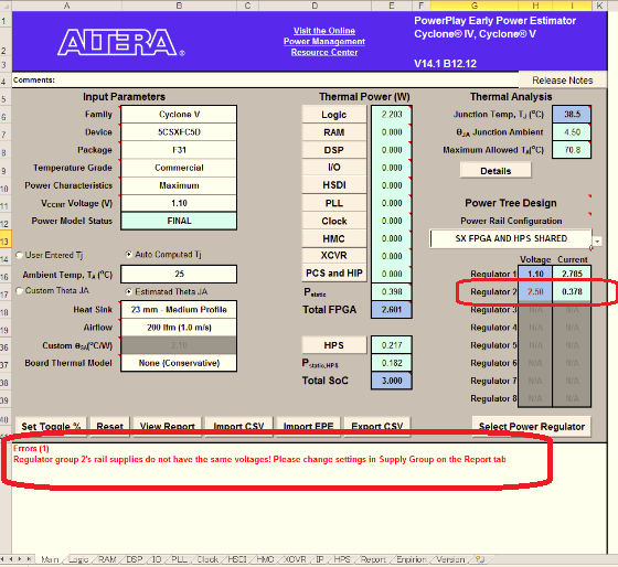
- When you return to the Main tab, the current consumption increases due to the above settings, and a warning is displayed in red. (see image 03)
Clear warning
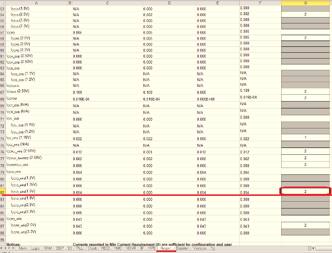
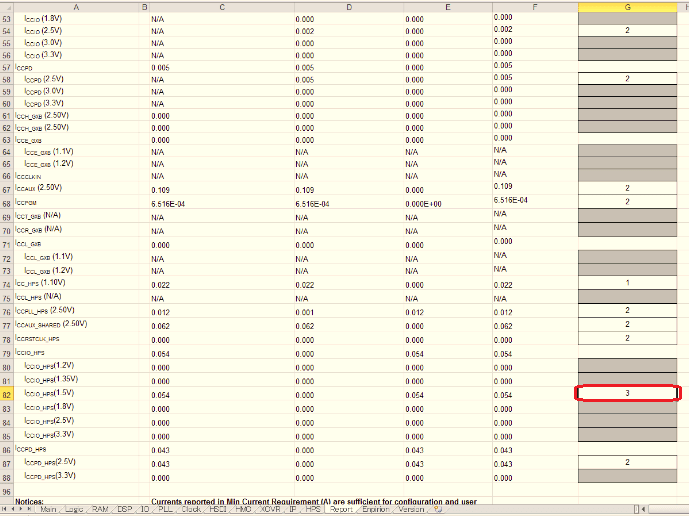
- If you select the Report tab, you'll see that two different voltages that should be distinguished are now one power rail. (see image 04)
- Since it can be confirmed that 1.5V is mixed up with the 2.5Vin rail, increase the rail by changing the value of the Regulator Group of the 1.5Vin rail from 2 to 3. (see image 05)
- The error has been resolved and the number of regulator groups has increased. (See image 06)
The above is a concrete example of confirming the necessary power rail using EPE. However, depending on your design, it may require additional current consumption or additional power rails. Please use EPE while checking each time.