- 半導体事業HOME
- マクニカの製品・サービス
-
技術情報

-
イベント・セミナー
- 取扱メーカー
- サポート
- お問い合わせ
- 製品購入はこちら
- 半導体事業のメルマガ登録
![]()
![]() 条件を指定して絞り込む
条件を指定して絞り込む
現在2168件がヒットしています。check

各レベルへのビット割り付けの工夫
前回、PAM4信号の4つの各レベルに対して、2ビットの情報を割り付けることを説明しました。
2ビットなので、とりうる状態としては(0,0)、(0,1)、(1,0)、(1,1)の4つとなります(カッコ内最初の値をMSB、後ろの値をLSBと表現します)。
この4つ状態を、PAM4の4つのレベルに割り付けることを考えます。
図1のビット割り付けで伝送する場合の、受信側でのビット誤りを考えてみます。
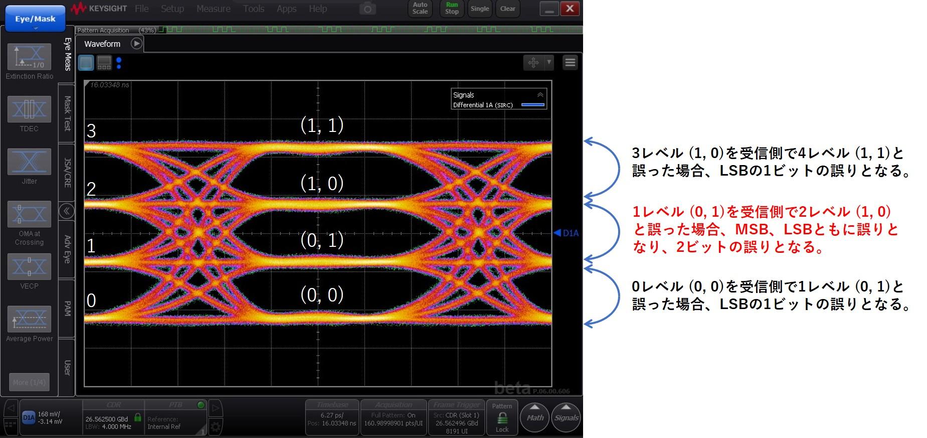
図1. PAM4の4レベルに対するビット割り付け(binary code)
送信側から0レベル (0,0)として送信された信号を、受信側で1レベル (0,1)と認識してしまったとしましょう。
この場合、MSBは0の情報が正しく0と伝わりますのでエラーとはなりませんが、LSBは0が1と認識されてしまうので、1ビットエラーとなります。
では、次に送信側から1レベル (0,1)として送信された信号を、受信側で2レベル (1,0)と認識してしまった場合を考えます。
この場合、MSB、LSBともにエラーとなりますので、ビットエラー状態はさらに悪化し、2ビットエラーとなります。
前回説明の通り、PAM4ではNRZに比べて各レベル間の振幅差が1/3になりますのでSNRも1/3となり、エラーしやすい伝送方法であることに間違いはないのですが、これを少しでも解消するために実際のビット割り付けは下記のようになっているのが普通です。
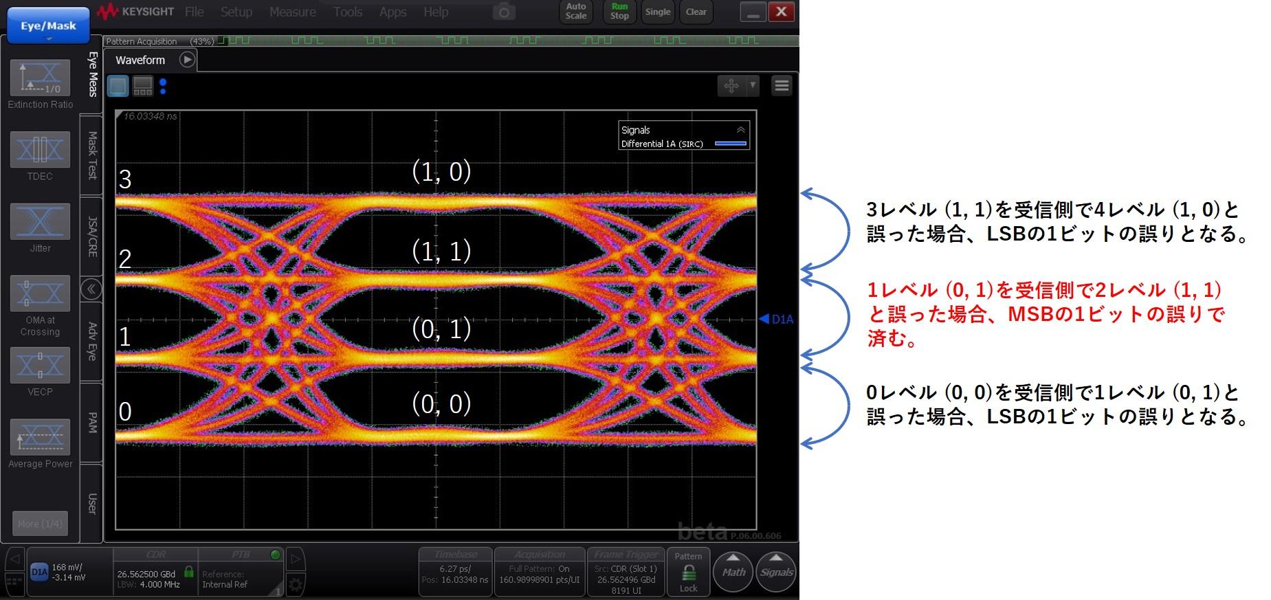
図2. PAM4の4レベルに対するビット割り付け(gray code)
図2の通り、実際の伝送におけるビット割り付けは0レベル側から順に、(0,0)、(0,1)、(1,1)、(1,0)となります。
送信側から0レベル (0,0)として送信された信号を受信側で1レベル (0,1)と認識してしまった場合のビットエラー状態はbinary codeの場合と変わりありませんが、1レベル (0,1)として送信された信号を受信側で2レベル (1,1)と認識してしまった場合は、binary codeの時と異なりMSB1ビットのみのエラーで済みます。
このように、エラーが発生しやすい伝送方式であっても、少しでもビットエラーを低減するための策が取られています。
なお、これまでの説明からわかるように、ビットエラーレシオの観点では、MSBよりもLSBの方が悪くなります。
FECの採用
FECとは、Forward Error Correction(前方誤り訂正)の意味です。
上述の通り、PAM4は伝送エラーが発生することを前提としているため、このエラーを訂正するためにFECを採用しています。
FECは受信側でエラーを訂正出来るための情報を送信信号にオーバーヘッドとして付加することで、エラーフリーの実現を図るものです。
IEEE802.3において、200GAUI-4や400GAUI-8などPAM4を前提とするインターフェース仕様では、Read Solomon FEC(RS-FEC、RS(544,514))を使用することが定められています。
Ethernetでの25G NRZ伝送容量は25.78Gbpsなので、PAM4とすることにより伝送容量は2倍の51.56Gbpsとなりますが、FEC符号化によるオーバーヘッドが付加されるため、FEC符号化された信号の伝送レートは53.12Gbpsとなります。
IEEE802.3では、ビットエラーの発生が十分にランダムである前提で(バースト的なエラーの発生がない、deterministicなエラー要因がない、など)、この符号化されたPAM4信号を受信側で復号化する前のビットエラーレシオ (Pre FEC BER) として2.4E-4未満とすることを定めています。
実際には伝送上のエラー要因は様々なので、FEC復号化後のビットエラーレシオ(Post FEC BER)として安定したエラーフリー状態が得られるように、Pre FEC BERを2.4E-4よりも低減させられるような伝送線路上でのエラー低減対策が重要です。
Broadcom社PAM4光トランシーバーソリューション
Broadcom社では、PAM4光トランシーバー製品を展開中です。
400Gbps DR4 (500m) Ethernet Transceiver AFCT-91DRDHZ
400Gbps DR4+ (2Km) Ethernet Transceiver AFCT-91DRPHZ
100Gbps DR (500m) Ethernet Transceiver AFCT-89SDHZ
100Gbps FR (2km) Ethernet Transceiver AFCT-89SFHZ
100Gbps LR (10km) Ethernet Transceiver AFCT-89SLHZ
お問い合わせ
ご興味のある方はぜひお問い合わせください。
Broadcom メーカー情報Topへ
Broadcomメーカー情報Topに戻りたい方は以下をクリックしてください。