- Semiconductor BusinessHOME
- Products and Services of Macnica,Inc.
-
technical information

-
Events and Seminars
- Handling Manufacturer
- Support
- Inquiry
- Click here to purchase products
- Semiconductor business e-mail magazine registration
![]()
![]() Narrow down by specifying conditions
Narrow down by specifying conditions
現在2189件がヒットしています。check

100G optical transceiver with NRZ interface
Currently, 100G QSFP28 optical transceivers are the mainstream in many network equipment, including data centers.
These mainly conform to standards such as 100GBASE-SR4, LR4, and CWDM4, and the electrical side interface between switch ICs on the board is 25Gbps NRZ x 4 lanes (CAUI4 C2M: Chip to Module). It is Inside the optical transceiver, mutual conversion between electrical and optical signals is performed for each lane.
Depending on the standard, there is a difference in whether this optical signal is multiplexed and output on a single optical fiber for transmission and reception, or whether it is output on a parallel optical fiber with 4 lanes. Optical signals are handled in 4-lane transmission in the same way as electrical signals.
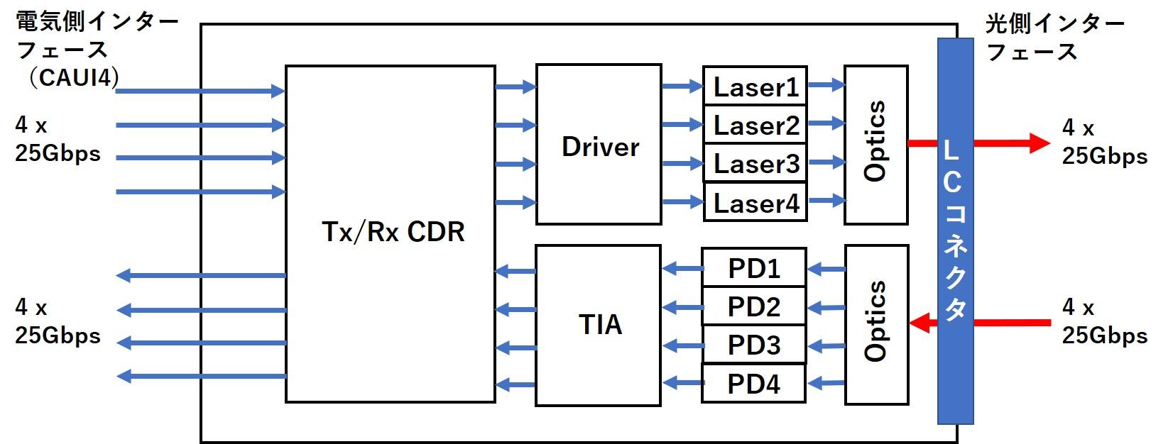
Figure 1 100GBASE-CWDM4 optical transceiver configuration block diagram
400G optical transceiver with PAM4 interface
On the other hand, the speed of network interfaces and transmission capacity per port continue to increase, and 400G QSFP56-DD optical transceivers are currently being commercialized. The QSFP-DD optical transceiver uses PAM4 (Pulse Amplitude Modulation 4) on both the electrical side and the optical side, while having commonality with the existing QSFP+ and QSFP28 optical transceivers in terms of housing dimensions.
The number of lanes on the electrical side interface is 8 lanes (50G/lane) due to lane expansion for 400G. Due to this lane expansion, the connector shape of the electrical side interface has twice the signal density of the conventional QSFP+, and has a form factor name of -DD (Double Density). On the other hand, the optical side interface is 4 lanes (100G/lane) like QSFP28 (excluding 400GBASE-SR8).
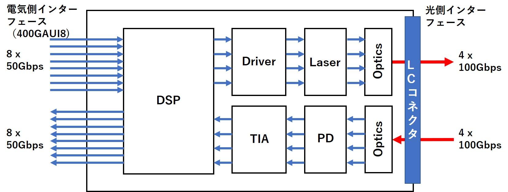
Figure 2 400GBASE-SR4 optical transceiver configuration block diagram
Difference between NRZ and PAM4 waveforms
As mentioned above, the outer dimensions of the housing of the optical transceiver are determined with backward compatibility in mind, so there are restrictions on the number of optical components that can be incorporated. Therefore, even if the purpose is to increase the transmission capacity, the number of lanes cannot be increased recklessly. For this reason, instead of increasing the number of lanes, PAM4 was adopted as a method of increasing the transmission capacity per lane.
The waveform differences between conventional NRZ transmission and PAM4 transmission are shown below.
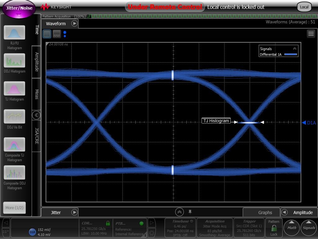
Figure 3-1 NRZ electrical waveform example
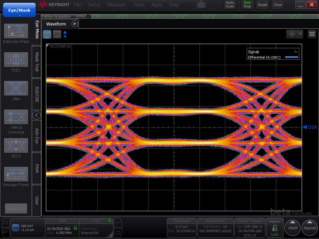
Figure 3-2 PAM4 electrical waveform example
As you can see from the waveform, NRZ is a 1-bit binary signal of 0/1, while PAM4 is a 4-level signal.
In NRZ, the state of each voltage level of 0 and 1 becomes the logic level (High or Low) as it is, but in the case of PAM4, these four voltage levels do not directly indicate the logic level. 2-bit information is assigned to each and transmitted.
In the above waveform, the time width between crosspoints (UI, Unit Interval) is the same for both NRZ and PAM4, but PAM4 transmits 2 bits within the same unit time as NRZ transmits a 1-bit signal. Since bit information can be transmitted, the transmission capacity is doubled.
Advantages and disadvantages of PAM4 interface
merit
The only way to double the transmission capacity with NRZ is to halve the UI, but as mentioned above, PAM4 can double the transmission capacity with the same UI as NRZ. The same UI means that the baud rate (a unit that indicates how many times a signal can be modulated and demodulated per 1 sik second) is the same.
For this reason, in the transmission line design on the board, there is less technological leap from the existing design than doubling the transmission capacity with NRZ, and it can be applied relatively early.
Demerit
Two new voltage levels are added between the voltage levels that represented 0 or 1 in NRZ, so the amplitude between each level is approximately 1/3 of NRZ. This means that SNR will be 1/3 of NRZ. Due to the reduced noise immunity, error-free transmission at the receiving end cannot be expected like NRZ.
Next time preview
Next time, I will explain the measures to achieve error-free operation.
Broadcom's PAM4 Optical Transceiver Solution
Broadcom is rolling out PAM4 optical transceiver products.
400Gbps DR4 (500m) Ethernet Transceiver AFCT-91DRDHZ
400Gbps DR4+ (2Km) Ethernet Transceiver AFCT-91DRPHZ
100Gbps DR (500m) Ethernet Transceiver AFCT-89SDHZ
100Gbps FR (2km) Ethernet Transceiver AFCT-89SFHZ
100Gbps LR (10km) Ethernet Transceiver AFCT-89SLHZ
Inquiry
We have many other products in addition to the above, so please visit the Broadcom optical transceiver product website and contact us at the number below.
Broadcom manufacturer information Top
If you want to return to Broadcom manufacturer information Top, please click below.