- 半導体事業HOME
- マクニカの製品・サービス
-
技術情報

-
イベント・セミナー
- 取扱メーカー
- サポート
- お問い合わせ
- 製品購入はこちら
- 半導体事業のメルマガ登録
![]()
![]() 条件を指定して絞り込む
条件を指定して絞り込む
現在2183件がヒットしています。check
パスコン
プリント配線板(ボード)に搭載される IC には、電源のパスコンを接続します。ところで、パスコンは日本語です。英語では、Bypass Capacitor(バイパスキャパシタ)といいます。ちなみに、「コンデンサ」も、20世紀初頭までは「Condenser」が用いられましたが、現在では、英語圏では、通常「Capacitor」と言います。
とはいっても、ここでは、日本語として定着している「パスコン」を用います。
パスコンの役割
言うまでもなく、電源のノイズの除去です。ノイズ源は、電源電流の変化によって生じます。
電流 i とキャパシタ C およびその端子電圧 v の関係は、
Cv=∫idt
で表されます。上式の左辺は、キャパシタの容量と電圧の積、右辺は電流の積分で、いずれも電荷です。
ノイズは、電圧として現れます。上式の v です。v と C とは反比例するので、C を大きく選ぶとノイズの電圧 v が小さくなることが分かります。したがって、まず、ある程度大きな容量のキャパシタ(パスコン)が必要です。
パスコンの直列共振と並列共振
『電源キャパシタの共振』を参照ください。
パスコンは、理想のキャパシタに直列に、抵抗とインダクタとが接続されています。RLC の直列接続による共振は、直列共振で、共振点で直列インピーダンスが最小になり、共振点以上の周波数ではインダクタが支配的となります。大きな容量のキャパシタを用いると、共振点が低くなり、高い周波数成分のノイズを除去することは難しくなります。そこで、大きな容量のキャパシタに並列に、容量の小さなキャパシタを接続すると、直列共振点が高くなるのでうまくいきそうです。
ところが、複数のキャパシタが並列接続されると、並列共振が生じます。したがって、より多くの、容量値の異なるキャパシタを並列接続して、並列共振点を互いに打ち消すようにします。
PDN ツール
上で述べた、複数のパスコンの数と容量とは、PDN ツールにより決めることができます。『電源供給ネットワーク(PDN)解析ツール』を参照ください。
PDN ツールによって、広い周波数帯域に対して、電源のインピーダンスが、ある値以下に設定できます。
よくある質問として、
- PDN ツールで求めた個数が少ないのだけど大丈夫か?
- パスコンへの配線長の影響は?
- パスコンの電源/温度特性で、値が減少したときの影響は?
- 他の電源と分離する場合の問題
などがあります。
PDN ツールでは、対象とする周波数帯域におけるターゲットインピーダンスを求めます。周波数帯域とターゲットインピーダンスがきちんと考えられているならば、PDN ツールで求めたパスコンの容量と個数で必要十分です。なお、ターゲットインピーダンスは、許容の電圧変化を、電流変化で割ったものです。
パスコンへの配線長
電源層に直結ではなく、層から配線で IC に供給する場合には、この配線のインピーダンスを考慮する必要があります。例えば、パターン幅が 1mm なら、特性インピーダンスは 10Ω 程度となります。電流変化が 100mA とすれば、配線が長いと、特性インピーダンスと電流の積の 1V のノイズが発生します。実際には、配線長が短いので、パターンの伝搬遅延時間 τ(ギリシャ文字小文字のタウ)の 2倍、すなわち 2τ と、ノイズの立ち上がり時間 tr との比に比例します。ノイズの立ち上がり時間が 500ps として、電源のパターン長を 5mm とすると τ=35ps なので、35/500=70mV となります。
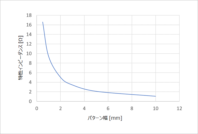
なお、直流抵抗は、1mm 幅で長さ 5mm なら、3mΩ 程度なので、100mA の変化に対して 0.3mV と、特性インピーダンスによ電圧変化に比べて無視できます。このノイズを低減させるには、電源のパターン幅を広く、短くします。パターン幅を広くすると特性インピーダンスが下がります。2mm なら 5Ω になります。図1 に特性インピーダンスの解析例を示します。
パスコンの容量が不足した場合
パスコンは、電流の急変分をまかなうだけの電荷を貯めるイメージです。貯めた電荷が十分なら、少々汲み出しても電荷の減少分はわずかです。
セラミックキャパシタは、その材料によって、容量の電圧依存性が存在します。これは、強誘電体の P-E(分極-電界)特性の非線形性に起因します。静電容量は、dP/dE に比例しますが、電圧(すなわち電界)が高くなると、傾きが寝てくるからです。また、強誘電体の P-E 特性は、多くの場合、温度依存性があります。
ノイズ(電圧)は、上述のように、C に反比例します。なお、実際には、ESR が存在するので、完全な比例ではありません。
0.1uF の指定に対して、0.080uF になると、ノイズが 25% 増加します。マージンの話しなので、ノイズが 25% 増えたら FPGA の動作にどのように影響するかは、実際の装置に対して、電源ノイズを加えて、振幅に対する誤動作の率を、長時間かけて、いろいろなシステムのプログラムに対して調べる必要があります。
電源ノイズによる誤動作は、信号の変化時に重なった場合のタイミングの増減が典型的な例です。
実験で調べるなら、信号の変化のタイミングにわざとノイズ重ねて、クロックを変化させて、誤動作率を調べる方法があると思います。電源にノイズを重畳させるには、パルストランスなどを用いるとよいでしょう。
他の電源との分離
よりきれいな電源を得たいために、チョークコイルなどを介して、電源を分離することがあります。特に、O/E (Optical Electronic) 変換回路や PLL 回路の電源が対象になることが多いようです。チョークコイルはインピーダンスが高いので、PDN ツールで実現した電源の低いインピーダンスは無意味となり、高い電源インピーダンスとなります。そこで改めて、分離した電源に複数のパスコンを接続する必要があります。すなわち、改めて PDN ツールを適用するわけです。メインの電源に比べると、パスコンの数と種類が少ないので、特に、対象の回路の敏感な周波数に、並列共振が起こっていないかを確認する必要があります。
おすすめ記事/資料はこちら
======================================
碓井有三のスペシャリストコラムとは?
基礎の基礎といったレベルから入って、いまさら聞けないようなテーマや初心者向けのテーマ、さらには少し高級なレベルまでを含め、できる限り分かりやすく噛み砕いて述べている連載コラムです。
もしかしたら、他にも気になるテーマがあるかも知れませんよ!
こちら から他のテーマのコラムも覗いてみてください。