- Semiconductor BusinessHOME
- Products and Services of Macnica,Inc.
-
technical information

-
Events and Seminars
- Handling Manufacturer
- Support
- Inquiry
- Click here to purchase products
- Semiconductor business e-mail magazine registration
![]()
![]() Narrow down by specifying conditions
Narrow down by specifying conditions
現在2004件がヒットしています。check

This is Sasaki in charge of power supply dock technology.
In this column, I would like to introduce some examples of problems related to power supplies that I encountered multiple times during various customer support sessions.
A customer contacted us and asked for information on the placement of capacitors.
For analog circuits, the layout is also part of the schematic!

Looking at the data sheet, it states that the power line capacitor should be placed close to the IC, but since it is placed as a filter, is it okay to place it in the power line even if it is not particularly close to the IC? ?

Ideally, it should be placed close to the device...
By the way, which part do you put it in? Could you show me the layout drawing?
This is the circuit diagram. Are there any problems?
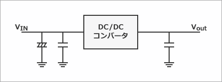
....
I would like to see the artwork (layout) of the board instead of the circuit diagram...
Please confirm that there are no problems with the capacitor placement or wiring method.
Does the artwork change anything? If the circuit diagram is correct, there is no problem, right?
The circuit diagram is in an ideal state, so if you really want to check the circuit, look at the artwork to see if the parts placement and wiring pattern are thin. I have to check etc.
Otherwise, the circuit may malfunction, even if the schematic is correct.
Really? ! The artwork has never been checked by a printed circuit board shop. . .
I thought there would be no problem because I had them design it while referring to the precautions in the datasheet. . .
Let me check.
Ah, the wiring for the power supply and ground is getting longer. I think the noise in the power supply circuit is getting louder, what do you think?
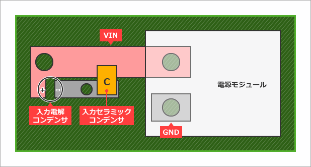
Yes, actually, it's noisy, so I was thinking of not using this power module on my next board.
The capacitor's GND connects to the power module's GND via a through-hole and passes through the inner layer, but it is ideal to connect the capacitor and power module with a thick GND line on the surface layer.
Ideally, the VIN electrolytic capacitor should also be connected to the power module without going through a through-hole, rather than entering the power module through a through-hole.
From now on, I will pay attention not only to the circuit diagram, but also to the artwork!
The point of this time
When checking the power supply circuit, it is essential to check not only the circuit diagram but also the artwork!
Click here for recommended articles/materials
Click here for recommended seminars/workshops
Analog solution power supply design seminar
Analog solution thermal design seminar
Basic seminar on power supplies for digital circuit designers