- Semiconductor BusinessHOME
- Products and Services of Macnica,Inc.
-
technical information

-
Events and Seminars
- Handling Manufacturer
- Support
- Inquiry
- Click here to purchase products
- Semiconductor business e-mail magazine registration
![]()
![]() Narrow down by specifying conditions
Narrow down by specifying conditions
現在2168件がヒットしています。check

hello. It's phi.
This time, I will introduce a stumbling block in voltage measurement after mounting a component on a PCB board.
first implement
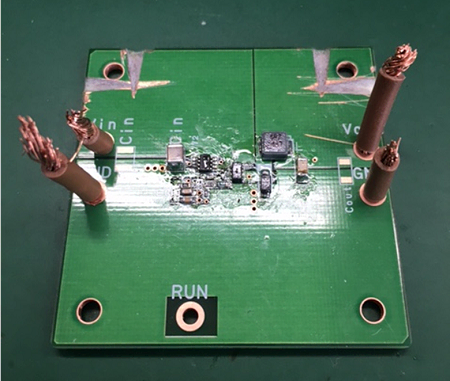
I soldered the components to the circuit board that I checked for continuity last time (Fig. 1).
Generally, it seems to be done using a machine, but I soldered the parts one by one by hand, so it was very difficult to attach small parts.
Checking the output voltage
After finishing the soldering somehow, next check if the board is working properly.
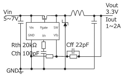
The DCDC converter I made this time outputs 3.3V with 5 to 7V input (Fig. 2), so I input 5V and 7V and checked the output value.
If you measure the output voltage when 5V and 7V are input. . .
Output voltage: 3.3V
Success! !
I was very happy.
Next, check the ripple voltage and frequency characteristics (Fig. 3).
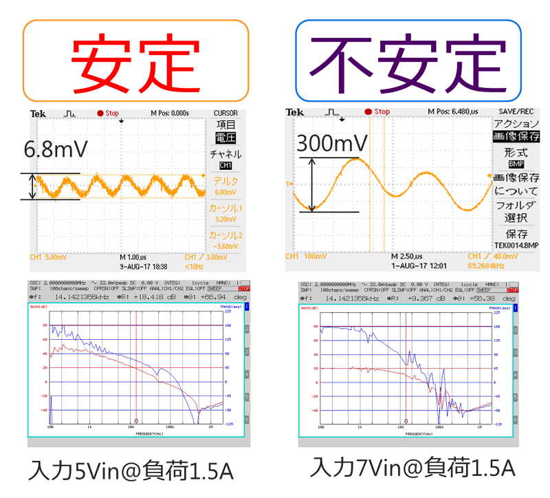
Looking at the ripple voltage, it is stable when the input is 5V, but when the input is 7V, it fluctuates greatly and becomes unstable.
Also, when comparing the frequency characteristics, the graph for 7V input has a jagged "sawtooth" shape compared to that for 5V input.
One possible cause of these problems is that the board is not energized, but since we have already confirmed that it is energized by conducting a continuity check in advance, we need to stabilize it using another method.
This is where "phase adjustment" comes into play.
Phase adjustment?
Phase adjustment is to adjust the values representing the stability of the power supply (crossover frequency, gain margin, phase margin) by changing resistors and capacitors to stabilize the power supply.
In order to stabilize the power supply, each value must be adjusted as follows.
・Crossover frequency … About 1/10 of the frequency of the power supply (The frequency of the power supply IC this time is 550kHz, so around 55kHz)
・Gain margin … -10dB or less
・Phase margin … 60deg or more
Change the resistors and capacitors circled in red in Figure 4 to get closer to this value.
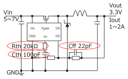
However, I had no idea how to change the values of the resistors and capacitors to stabilize the power supply.
Keep going for less than a week...
I was able to get the following results.
Vin=7V, Load: 1.5A Actual measurement Ideal crossover frequency [kHz] Around 51.555KHz Gain margin [dB] -13.1 ≤ -10dB Phase margin [deg] 61.2 ≥ 60deg
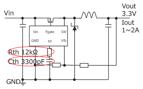
The final stable circuit is shown in Figure 5.
I removed the capacitor (Cff in Figure 3) that was connected in parallel with the feedback resistor, and changed the value of the resistor and the capacity of the capacitor that were connected in series to the Ith pin.
Measure the ripple voltage again!
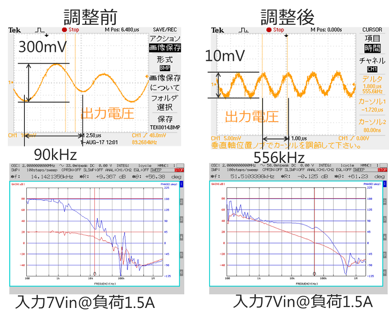
Looking at the graph after phase adjustment, the ripple voltage is very small at 10mV, and the graph of frequency characteristics is smooth.
Phase adjustment, managed to succeed! !
At the end
Phase adjustment was more difficult than I imagined. . .
I learned that the people involved in the design are doing steady work every day, like walking along walls in the dark.
In the future, as an FAE, I will devote myself to proposing power supplies and designs that do not cause problems for our customers.
Next time, I will talk about the evaluation of DCDC converters. looking forward to!
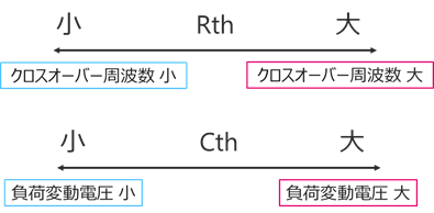
bonus
I will describe the relationship between the values of the resistor Rth and the capacitor Cth and the phase adjustment parameters, which I found during the trial and error of one week.
I would appreciate it if you could help me with the phase adjustment.