
![]()
![]() Narrow down by specifying conditions
Narrow down by specifying conditions
現在1887件がヒットしています。check

Introduction
Hello. It's phi.
This time, I would like to introduce a stumbling block and a failure story in the selection of parts and hand assembly of the DCDC converter production practice.
I would be happy if you read it while remembering when you were a newcomer.
Stumbling in part selection
After deciding on the DCDC controller to use, the LTC3772, we moved on to selecting peripheral components.
Peripheral parts include the following (Fig. 1).
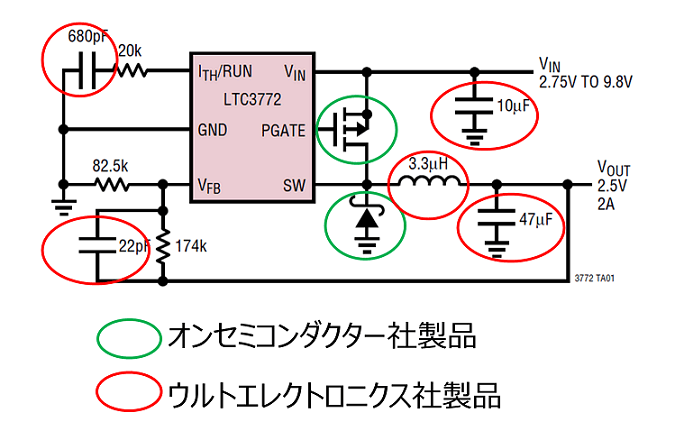
Peripheral parts were solidified with products of ON Semiconductor and Ult Electronics, which are handled by Ultima.
However, I hit a wall in the selection.
I can't read the datasheet
When selecting parts, it is essential to check the datasheet to know what the part is.
However, I couldn't read the datasheet, so I had a lot of trouble.
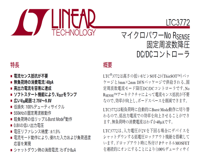
Below is the data sheet for the LTC3772. This is written in Japanese, but I still can't read it.
(The datasheets for other products are in English, so I can't read them too much.)
First of all, I do not know what is written.
I don't know where it is written.
And I don't even know what the word means.
In this way, it was full of "things I don't know".

There have been many times.
I wondered how seniors could find what was written on the datasheet so quickly.
Little by little, I got the hang of it by reading through one datasheet all at once.
By reading many datasheets, my seniors were able to quickly find the information they needed.
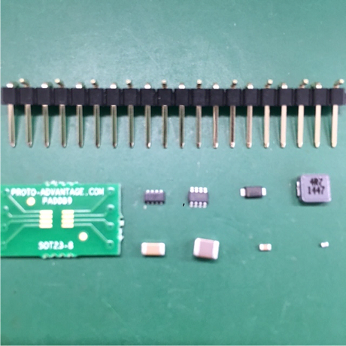
After somehow reading the data sheet and purchasing the necessary parts, the next step is hand assembly.
failure by hand
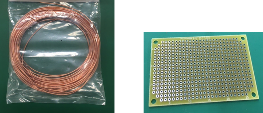
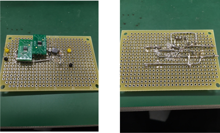
The parts that arrived (Fig. 3) were attached to the universal board using polyurethane copper wire.
And here is the finished product (Fig. 5).
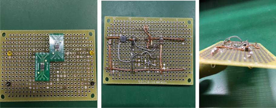
This time, I attached a chip resistor to the universal board, but the wiring was not clean and ended up being an air wiring.
Will this be all right?
Then I checked the continuity and applied voltage.
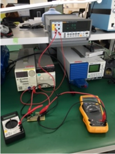
As a result, the output voltage is 0V. There was no current and it was a shock.
The cause was poor solder contact.
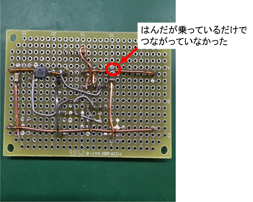
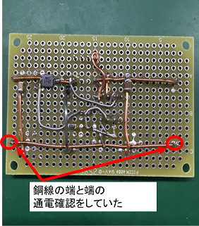
I didn't notice it because I only checked the energization of the copper wire when checking the energization. . .
It was a fairly elementary mistake, but it was a big one for me.
Because I knew that the cause of the malfunction of the electric circuit was in the electric circuit.
In other words, I learned the lesson that "Electricity doesn't lie."
Hands finally done!
In order not to repeat the previous mistake, I did some manual assembly again and managed to complete the prototype board.
When I applied the voltage, I was able to confirm that the output voltage was 3.3V!
I was very happy.
Summary
This time, I wrote about how to read the data sheet and how to set it up.
I learned a lot from many failures.
- Everything is written in the data sheet
・Electricity does not lie because the cause of failure is always in the circuit.
When I become a senior, I feel like I'll say, "Everything is written in the datasheet!" (laughs)
I would like to make use of these learnings in the future.
Next time we look forward to!