- Semiconductor BusinessHOME
- Products and Services of Macnica,Inc.
-
technical information

-
Events and Seminars
- Handling Manufacturer
- Support
- Inquiry
- Click here to purchase products
- Semiconductor business e-mail magazine registration
![]()
![]() Narrow down by specifying conditions
Narrow down by specifying conditions
現在2189件がヒットしています。check

Recently, the AC accuracy requirements for FPGA core voltages have become more and more stringent, and within 45mV (0.9V±5%) is required. Therefore, if the correct measurement method is not used, the power supply noise may be judged to be large.
In this article, we compare how different accessories used at the tip of the power rail probe affect the ripple voltage measurement results of switching regulators.
Effects of Power Rail Probe Accessories on Waveform Measurements
In the previous article "Is that measurement correct? The true ripple voltage was 1/3” and recommended the measurement of the power rail probe.
This time, we will compare the difference in ripple measurement results with the following two accessories that can be used with the power rail probe.
① Substrate type flex chip
②MMCX (Micro Miniature Coaxial) connector
Evaluation environment
This time, we used the LT8609S evaluation board, which is Analog Devices' 42V withstand voltage synchronous rectifier MOSFET built-in step-down DCDC.
Evaluation board settings
The change from the original evaluation board is to change the feedback resistor R5 from 182KΩ to 300KΩ and set the output voltage to 3.3V.
Evaluation conditions: Input voltage 12V, output voltage 3.3V, load current 2A, switching frequency 2MHz setting

Measurement environment
・Stabilized power supply KIKUSUI PAN35-20E is used. Connect between VIN and GND on the evaluation board.
・Electronic load KIKUSUI PLZ164 is used. Connect between VOUT and GND
・Oscilloscope Tektronix 6 series is used. Ripple observed across output capacitor C6.
- With Power Rail Probe TPR1000.
- Accessory 1.3m, SMA(Ma) - MMCX (Ma) , 50Ω cable
- Accessory Tektronix Flex Tip (Board type)
- Accessory MMCX connector (Wurth Elektoronik 66012002111503)
Ripple voltage measurement results comparing accessories
This time, we prepared two power rail probe accessories and compared the results of measuring the ripple voltage of a switching regulator (Fig. 2).
Uses Tektronix flex tip (substrate type)
This is the waveform on the left side of Figure 2. About 14mV peak to peak was observed.
With MMCX connector (Wurth Elektoronik 66012002111503)
It is the waveform on the right side of Figure 2. About 7mV peak to peak was observed.
The results show that the ripple is twice as large when using the flex tip.
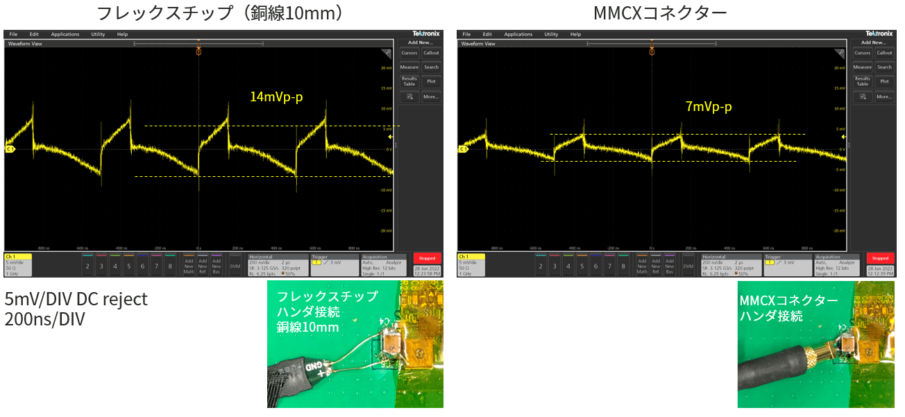
Figure 2: Ripple voltage measurement results
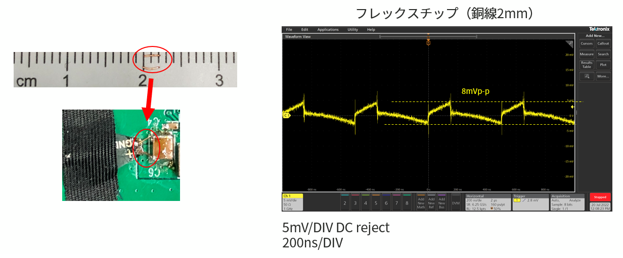
Try changing the copper wire length of the flex tip
We presume that the reason why the flex chip has twice the ripple compared to the MMCX connector is the influence of the 10 mm copper wiring of the flex chip, and we decided to confirm the possibility of the influence of the impedance of the copper wiring. did. Here, I tried to verify how close the measurement results would be when using a MMCX connector by setting the copper wiring to 2mm.
As shown in Fig. 3, by reducing the copper wiring to 2mm, it improved to 8mVp-p, which is almost the same as the MMCX connector.
At the end
When using the flex chip (copper wire 10 mm), the output voltage ripple is 14 mVp-p, but when using the MMCX connector, it was confirmed that the output voltage ripple waveform is 7 mVp-p, which is about half.
By shortening the copper wiring of the flex chip from 10 mm to 2 mm, we obtained 8 mVp-p, which is almost the same measurement result as when using the MMCX connector.
From this experiment, we learned that it is desirable to consider the influence of the impedance of the tip of the accessory used when it is necessary to accurately measure voltage changes as small as a few millivolts.
The measurement results of MMCX were good, and it is recommended to prepare a connection pattern and through holes for easy installation. This time, since it is an evaluation board, there is no pattern, so I processed the connector and connected it directly to the output capacitor. When connecting directly to a component, the bending of the SMA-MMCX cable will apply considerable force, and it is easy to damage the connected component, so be careful.
In the case of flex-chip copper wire, the use of 10mm makes connection easier, but experimental results show that the error in measurement results increases due to the high impedance. In order to obtain the measurement result, it is necessary to process and connect to a 2mm copper wire. In that case, the copper wire was quite short, so it was quite difficult to install. It was difficult to cut to 2mm, and I had a hard time soldering short copper wires.
Click here for recommended seminars/workshops
Click here for recommended articles/materials
LTspice List of articles: Let's use LTspice series
FAQ about power ICs: FAQ list
List of technical articles: technical articles
Manufacturer introduction page: Analog Devices, Inc.
Click here to purchase products
Click here for manufacturer site/other related links
Inquiry
If you have any questions regarding this product, please contact us using the form below.
Analog Devices Manufacturer Information Top
If you want to return to Analog Devices Manufacturer Information Top, please click the button below.