- Semiconductor BusinessHOME
- Products and Services of Macnica,Inc.
-
technical information

-
Events and Seminars
- Handling Manufacturer
- Support
- Inquiry
- Click here to purchase products
- Semiconductor business e-mail magazine registration
![]()
![]() Narrow down by specifying conditions
Narrow down by specifying conditions
現在2183件がヒットしています。check

This article describes the effects of external noise when measuring ripple waveforms of buck switching regulators.
Switching regulators are often thought of as noise sources on production boards and are considered "circuits that emit noise". Perhaps for this reason, we sometimes receive inquiries about the causes and countermeasures, assuming that all the noise we see with an oscilloscope when checking the waveform of a switching regulator is caused by the switching regulator.
This time, we will introduce an example of noise that became a problem when checking the waveform with an oscilloscope.
Ripple waveform measurement
In the previous technical article, "Is that measurement correct? The true ripple voltage was 1/3", I explained that the ripple voltage value differs depending on the probe.
As for the ripple measurement result at this time, we were able to observe a beautiful ripple like the waveform in Fig. 1. This proves that power rail probe measurements are valid.
However, until I got this result, I was in trouble because I was suffering from noise and could not acquire a clean waveform.
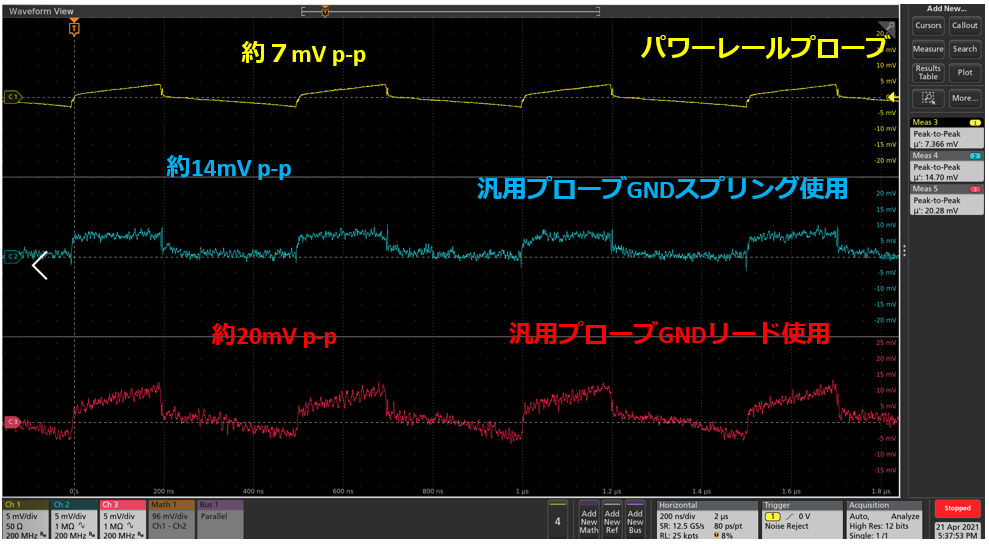
Figure 1: Ripple voltage measurement results
Initial measurement environment and ripple waveform
This time, we used the LT8609S evaluation board, which is a 42V withstand voltage synchronous rectifier MOSFET built-in step-down DCDC from Analog Devices.
Evaluation board settings
The change from the original evaluation board is to change the feedback resistor R5 from 182KΩ to 300KΩ and set the output voltage to 3.3V.
Evaluation conditions: Input voltage 12V, output voltage 3.3V, load current 2A, switching frequency 2MHz setting

Figure 2: LT8609S Evaluation Board Schematic
Measurement environment
・Stabilized power supply PWR801ML from Kikusui Electronics Co., Ltd. is used. Connect between VIN and GND on the evaluation board.
・Electronic load PLZ164 from Kikusui Electronics Co., Ltd. is used. Connect between VOUT and GND
・Oscilloscope Tektronix 6 series is used. Ripple observed across output capacitor C6.
- Use Power Rail Probe TPR1000 or General Purpose Probe TPP1000.
Ripple voltage measurement result
This time, I used two types of probes to measure the ripple voltage of a switching regulator.
A waveform like the one in Fig. 3 was obtained. Due to the noise that appears in the red frame, even if you try to obtain peak-to-peak measurement results, you will not be able to measure the correct value.
In the measurement using the GND lead, the GND loop becomes large and the effect of noise is large. Even power rail probes, which are less susceptible to noise, are affected by noise.
I reviewed the probing method many times, but it didn't improve, so I finally changed the power supply to the battery prepared for in-vehicle use and experimented.
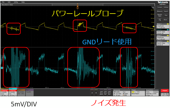
Figure 3: Ripple measurement results

Figure 4: Power Rail Probe

Figure 5: General purpose probe (using GND lead)
Replace the stabilized power supply with a 12V battery and measure
I changed the power supply from commercial power supply → stabilized power supply → evaluation board to battery → evaluation board connection.
Figure 6 shows ripple waveform results measured with a power rail probe when powered by a battery.
The noise that was in the shape until a while ago disappeared cleanly.
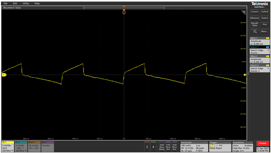
Figure 6: Ripple waveform when powered by battery
Summary
The ripple noise source was found to be noise from the mains or regulated power supply.
(Unfortunately, we have not been able to follow the separation of commercial power supply and stabilized power supply.)
In the future, there will be more opportunities to measure low-voltage ripple, so we were able to reconfirm the need to pay attention to input power supply noise when performing evaluations.
This time, there was a battery at the measurement site, so we were able to isolate the noise source.
As in this example, noise may be picked up by the measurement environment other than the measurement equipment, and the measurement may not be performed correctly, so caution is required.
In addition, we often receive requests from customers to do something about the noise in their switching regulators, as power supply noise degrades the signal quality of FPGAs. It was a good experience for me to say that I was troubled by power supply noise in the measurement environment, and I would like to propose and support future customer support so that they can design power supplies with less noise.
Supplement: In the experiment in the technical article "Is that measurement correct? The true ripple voltage was 1/3", I gave up the stabilized power supply and measured it with a battery.
Click here for recommended seminars/workshops
Click here for recommended articles/materials
Click here to purchase products
Click here for manufacturer site/other related links
Inquiry
If you have any questions regarding this product, please contact us using the form below.
Analog Devices Manufacturer Information Top
Analog Devices Manufacturer Information If you would like to return to the top page, please click below.