- Semiconductor BusinessHOME
- Products and Services of Macnica,Inc.
-
technical information

-
Events and Seminars
- Handling Manufacturer
- Support
- Inquiry
- Click here to purchase products
- Semiconductor business e-mail magazine registration
![]()
![]() Narrow down by specifying conditions
Narrow down by specifying conditions
現在2158件がヒットしています。check
![[Introduction to accelerometers] Lesson 13: Let's measure the angle with an accelerometer (Part 1)](/business/semiconductor/articles/140512_ADI_article_Cover_acel.png)
In the [Introduction to Accelerometer] series, we will explain the basic usage and application methods, focusing on analog devices' accelerometers. In this article, we measured the angle (tilt angle) using Arduino and ADXL345.
[Introduction to accelerometer] Click here for the series list
About the principle of angle (inclination) detection
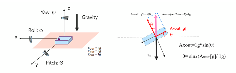
Articles introduced in the past 10th ~Let's remove gravitational acceleration~, I mentioned that a MEMS-type accelerometer like the ADXL345 can detect gravitational acceleration as a DC component (static acceleration). Therefore, the acceleration sensor can determine the tilt angle from the amount of orthogonal vector change of the axis due to gravitational acceleration. Familiar examples include digital camera levels, vertical and horizontal rotation of smartphone screens, and motion detection controllers for game consoles.
I created an image diagram below. When the device is placed in the direction of gravity as shown in the figure, the X and Y axes are horizontal axes perpendicular to the gravity axis (z axis). Also, the angular changes of the X-axis and Y-axis with this horizontal plane as the reference are called pitch and roll. Here, the roll angle when the Y axis is fixed and the X axis is rotated can be obtained from Ax[°]=ASIN(ax[g] / 1[g]). From this formula, the acceleration change per degree from 0° is about 17.4mg. Also, +1.0g when rotated +90° and -1.0g when rotated -90°.
For details, please refer to the following application note.
AN-1057: Detecting Tilt with an Accelerometer
Improving the accuracy of tilt measurement with an accelerometer
Next, let's consider how fine an angle can be measured (angular resolution). The resolution of the ADXL345 used this time is 10bit (3.9mg/LSB@±2g). Since the change acceleration per 1° is about 17.5mg, ideally there is an angular resolution of 3.9mg/17.5mg = about 0.2°. However, it is actually affected by noise, so it is necessary to consider noise specifications. Also, the accuracy of the angle (deviation from the true value) is affected by offset error and sensitivity error. Therefore, when precision is required, it is necessary to understand the parameters of the data sheet and design.
Please refer to the following application note for the estimation method.
Selecting the Best MEMS Accelerometer for Your Application [Part 1]
Let's measure the angle from the acceleration of gravity using Arduino
We will use the accelerometer "ADXL345" and the hardware open platform "Arduino" to calculate the amount of change in gravitational acceleration and create a sample program to find the tilt angle.
Things to prepare
Here is what I prepared to evaluate the accelerometer this time.
・PC with Arduino IDE installed (Download Arduino IDE from From here)
・ Arduino Nano compatible board
・ Accelerometer ADXL345
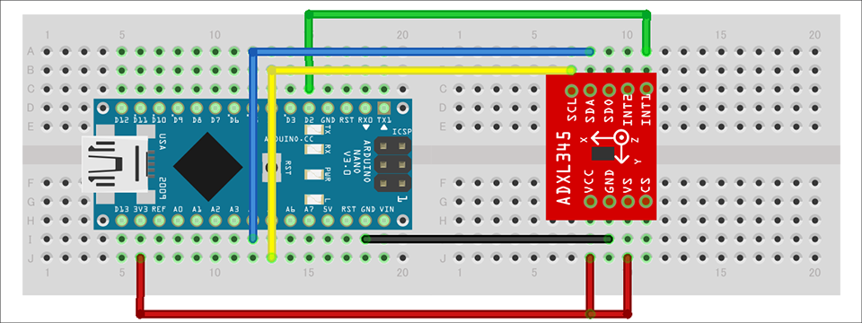
・Others (USB cable (for Arduino and PC connection), breadboard, wires)
Combine the above parts to form a circuit as shown in the figure below. Power supply to Arduino Nano is supplied by USB bus power from PC. The ADXL345 supports SPI and I2C interfaces, but this time we will use the I2C interface. It also uses the INT1 pin of the interrupt pin.
Program content
In this program, the calculation formula is Ax[°]=ASIN(ax[g] / 1[g]) to find the roll angle and pitch angle. The flow of the program acquires the acceleration of the X-axis and Y-axis. After that, I made it simple by converting it to an angle using the trigonometric function ASIN(). You can download the project file created with the Arduino IDE, so if you are interested, please get it from the "Document Download" below.
operation check
I checked the operation of the created program. As you can see in the video, changing the angle of the device confirmed that the roll and pitch angles on the serial console changed.
However, there were some areas of concern.
・The ideal angle when placed horizontally is 0°, but the actual angle is not 0°.
・As the angle approaches 90°, the accuracy of angle detection decreases.
・If the place where it is placed is vibrating, the vibration will be picked up, resulting in an error in the value.
I would like to discuss these points on another occasion.
This time, I measured the angle (inclination) with an acceleration sensor. I'm glad if you can use it as a reference.
Download the sample code verified this time
We provide the Arduino project file that we implemented this time. Please apply from here and give it a try.
About Accelerometer ADXL345
The ADXL345 used this time is a 3-axis digital output acceleration sensor. The main features are as follows.
・A standard accelerometer that is very easy to use with built-in ADC, operation function block, and FIFO
・Acceleration data adopts general I2C/SPI in digital serial method
・The 3-axis type sensor is a rectangular coordinate (X, Y, Z), and the acceleration acting on each axis can be obtained.
・The maximum detectable acceleration can be set in the range of 2g to 16g, and the sampling range is as wide as ~3.2kHz, so it can be applied to various applications such as impact, tilt, and motion detection.
・Flexible mode to reduce current consumption
For more information on the ADXL345, visit www.adxl345.com. data sheet Please refer to. Also, this accelerometer is very easy to use, so if you want to evaluate an accelerometer from now on, please try it on the evaluation board.
At the end
If you have any questions about the contents of this article, or if you have any problems with selecting or using accelerometers, please contact us from the following.
Analog Devices Manufacturer Information Top
If you want to return to Analog Devices Manufacturer Information Top, please click the button below.
![[Introduction to accelerometer] Thumbnail image of Let's use the interrupt function](/business/semiconductor/articles/9d56e574e3a24bcf3f076e91d90f4a53.png)