- Semiconductor BusinessHOME
- Products and Services of Macnica,Inc.
-
technical information

-
Events and Seminars
- Handling Manufacturer
- Support
- Inquiry
- Click here to purchase products
- Semiconductor business e-mail magazine registration
![]()
![]() Narrow down by specifying conditions
Narrow down by specifying conditions
現在2178件がヒットしています。check

Introduction
Hello, I'm Dophie.
Recently, I have been doing production practice as part of my technical training.
I made a home alarm.
When a person is detected, it is a device that generates an alarm with sound and light.
During the production training, I learned a lot. I would like to introduce it little by little from this time.
Beginning of production practice ~October~
I started production training with the aim of "using the knowledge and skills I have learned since joining the company to create a product that will be the culmination of my training."
The products I studied after joining the company are as follows.
・Power supply IC
・A/D converter
・D/A converter
・Operational amplifier etc.
Using the above analog products and knowledge, we will make a home alarm.
What is communication?
The first thing I stumbled upon was the concept of “communication,” as the title suggests.
Among the above products, A/D converters and D/A converters also handle digital signals, so "communication" is required for data transmission and reception.
Power supplies and other analog products are basically wired with conductors, which are used to electrically connect devices.
Typically, the portion of the line represented on the schematic is routed with conductors.
At first, I thought that wiring according to the circuit diagram with conducting wires = communication was possible.
The image in my brain at this time is Figure 1.

Briefly describe the processing of the device (see Figure 1).
1. The sensor sends a digital signal (High / Low)
2. Microcontroller receives and sends digital signal only when the signal is high
3. Convert digital signal to analog signal with D/A converter and output
Now that we have decided on the block diagram of the equipment, when I was thinking about selecting parts, a senior colleague pointed out to me.
Senior: “By the way, what are you using to communicate?”
I ``...!?
At first, I couldn't understand the meaning of my senior's point at all.
After further research, I found that in order to send and receive digital signals (data), "communication" was necessary. (Of course, you can't communicate just by connecting with conductors...)
I understood what the seniors pointed out, but at that time I was a complete beginner when it came to "communications."
From here, the days of investigation began, and as a result, we decided to adopt a communication method called "I2C communication of serial transmission".
Here, I would like to explain a little about "serial transmission" and "I2C communication".
serial transmission??
Serial means "in series".
As its meaning suggests, serial transmission sends serially arranged data bit by bit on a single line (Fig. 2).

Serial transmission (Fig. 2) requires only one line for data transmission, but requires parallel-to-serial data conversion on the transmitting side and serial-to-parallel data conversion on the receiving side.
I2C communication??
I2C (Inter-Integrated-Circuit), one of the serial transmission methods, has the following three characteristics.
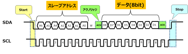
1. Data can be communicated using only two bus lines (SCL (clock line) and SDA (data line))
2. One master (controlling side) can set multiple slaves (controlled side)
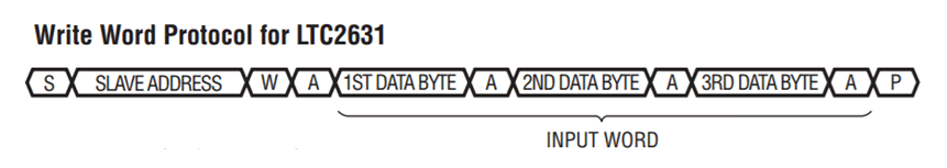
3. Each slave has an address, and the receiving side sends an "acknowledge" to the master for every 1 byte (8bit) transfer.
*The acknowledgment will be explained later.
In my device, I wanted to reduce the number of lines when designing the circuit, and because I had to set the A/D converter and D/A converter as slaves, I adopted I2C communication..
The theory is perfect. Now it's time to check the operation on the actual device!
Trouble Has Occurred!? ~No Acknowledgment Returns~
Now that I understand the theory, I tried I2C communication with an actual device.
But here comes the trouble.
Why didn't "acknowledge (see Figure 3)" come back!!?
An acknowledgment is a signal such as "connection is established" returned from the slave side when the address specified by the master side matches the address of the slave side to be connected.
If this is not returned, in my device it means that the microcomputer (master) does not recognize the D/A converter (slave).
First, I checked the address I specified on the master.
In I2C communication, the address is specified by a total of 8 bits of "slave address (7 bits) + transmission/reception specification bit (1 bit)".
The slave address of the D/A converter (LTC2631A-12) used is "0010000", and since it is a transmission (Write) this time, the 8th bit is "0".
Therefore, the address specified by the master is "00100000".
Therefore, in the microcomputer program, it is defined as 0x20 converted to hexadecimal.
Figure 4 shows the actual measured waveform.

If you look at Figure 4, you can clearly see something wrong.
I should have sent "00100000" data, but it is "01000000".
Also, if it is normal, the 9th bit should be Low ( 0 ) and the acknowledge should be returned, but the 9th bit was High ( 1 ).
why . . . .
⇒Continue to Part 2
at the end
During the production practice, I had a lot of trouble with "communication".
I still need to study. . .
Well, in the next article, I will introduce how I solved the "acknowledgement" problem.
Thank you for your next article.
Finally, we would like to introduce the analog IC manufacturers that we deal with.
Analog Devices
A leading manufacturer of high-performance standard analog ICs.
We determine the performance and quality of our customers' final products, such as amplifiers, battery management, data converters, high frequencies, interfaces, voltage regulators, and voltage references, and achieve stable supply.
In principle, we will not discontinue the production of our products, so customers who use our products for a long period of time, such as industrial equipment, can use them with peace of mind.
