- Semiconductor BusinessHOME
- Products and Services of Macnica,Inc.
-
technical information

-
Events and Seminars
- Handling Manufacturer
- Support
- Inquiry
- Click here to purchase products
- Semiconductor business e-mail magazine registration
![]()
![]() Narrow down by specifying conditions
Narrow down by specifying conditions
現在2159件がヒットしています。check

What are the advantages of automatic resettable electronic breakers?
Related information article "Electronic breaker made with current detection amplifier" can be reset by turning on the power again or resetting with the LE terminal (temporarily set to low) after removing the fault, but it is possible to remotely supply power to multiple slave units In the case of the parent device, it may be difficult to turn on the power again or provide a reset terminal for each port of the child device, or it may be more convenient to automatically return.
In such a case, it is useful to periodically retry and automatically return. This can also be achieved with the LT6118 with additional circuitry, but is easier with the LT1910.
High-side MOSFET driver LT1910 with protection
The LT1910 is an N-channel MOSFET driver with an integrated boost circuit and a current sensing circuit for short-circuit protection, enabling power supply circuit breaker applications. The 8V to 48V supply voltage makes it unsuitable for systems with supply voltages as low as 3.3V or 5V, but the built-in timer allows for a programmable auto-recovery time.
The features and functional block diagram of the LT1910 are shown below.
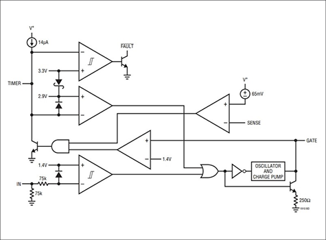
Features of the LT1910
- Supply voltage range: 8V to 48V
- -Includes protection against 15V to 60V power supply transients
- Short circuit protection
- Auto restart timer
- Open collector fault flag
- Fully operational N-channel MOSFET switch
- Programmable current limit, delay time, and auto-restart period
- Voltage limited gate drive
- Default off state when input is open
- Supplied in SO-8 package
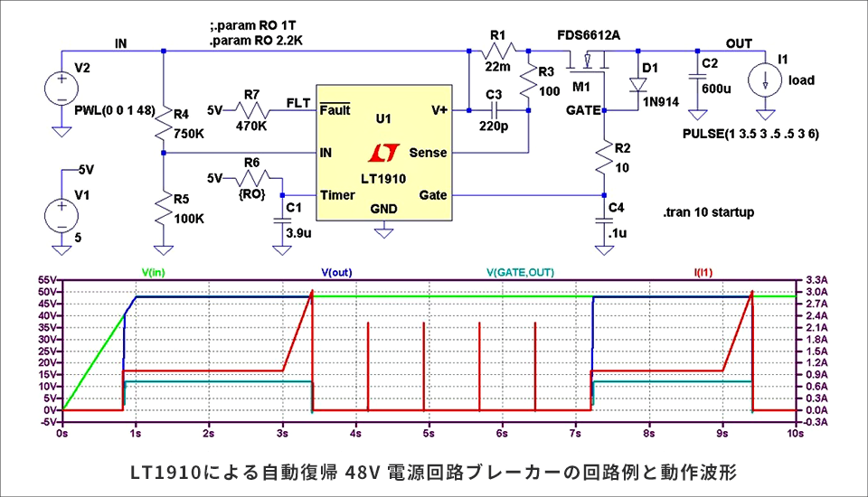
Example circuit and results using LTspice
Below is an example circuit with LT1910 using LTspice. Current detection is done with shunt resistor R1 and the limit is set when the voltage drop reaches 50mV. R3, C3, and C4 provide a delay time for detection to prevent detection with spike current. A capacitor connected to the Timer pin can be used to program the recovery time. In the above circuit example, the retry is performed approximately every 0.7 seconds, which greatly reduces heat generation when the output is shorted.
It is also possible to disable automatic recovery by pulling up to approximately 5V with a 2.2KΩ resistor. The Fault pin is pulled up to 5V, but since this is for checking the status, it can be left open if status display is not required. D1 is used to suppress the Vgs voltage for gate protection of MOSFET M1.
The IN terminal is originally a logic signal that drives the gate, but it is used for the UVLO (Under Voltage Lockout) function that prevents operation when the input voltage is below a certain level.
Click here for recommended articles/materials
To download LTspice, read this article.
LTspice article list: Let's use LTspice!
Inquiry
If you have any questions about Analog Devices products, please contact us here.