- Semiconductor BusinessHOME
- Products and Services of Macnica,Inc.
-
technical information

-
Events and Seminars
- Handling Manufacturer
- Support
- Inquiry
- Click here to purchase products
- Semiconductor business e-mail magazine registration
![]()
![]() Narrow down by specifying conditions
Narrow down by specifying conditions
現在2183件がヒットしています。check

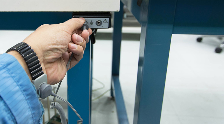
ESD (Electro Static Discharge) measures are taken to protect against system malfunction and device destruction due to static electricity.
For example, we use ESD circuits to prevent devices from being damaged by static electricity when an operator touches them during factory shipping inspections, and to prevent malfunctions of personal computers and communication systems in the market due to static electricity.
Did you know that there are device-level specifications and system-level specifications for such ESD specifications?
If a system ESD test is performed without knowing the difference between the device level and the system level of ESD, the device may be destroyed, or the product may be shipped without adequate countermeasures, resulting in defects in the market. so be careful.
device level
The most common provision is the test method known as HBM (Human Body Model). Many devices are designed with protective elements on each pin to hold 2KV.
Some people may think, "If 2KV is static-resistant, it won't break even if you don't wear a wrist strap!" Therefore, be sure to take measures against static electricity, such as using an earth ring.
system level
System-level ESD is tested using the IEC61004-2 method specified by the IEC (International Electrotechnical Commission). At level 3, contact discharge 6KV and air discharge 8KV are applied to the system to test whether the system malfunctions.
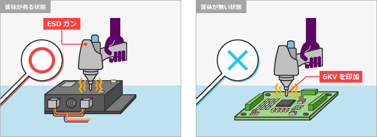
On rare occasions, there are engineers who simply test system ESD by applying 6KV from the top of the device with an ESD gun without a housing, but the device can withstand only HBM 2KV. Be careful as it deals damage.
How do you implement ESD countermeasures for a system that is difficult with a single device?
How to deal with system-level ESD
Let us consider the case of applying contact discharge of 6 KV to the connector of the interface. If you have a HBM 2KV device plugged into the connector, it will get 6KV applied to the device and it will be destroyed.
As a countermeasure, place a zener diode, TVS (transient voltage suppressor), or varistor, which are ESD protection elements, close to the connector.
On rare occasions, ESD protection elements have been seen to be placed near the device far from the connector. In this case, the applied ESD noise increases due to the inductance component of the wiring and may destroy the device. Pay attention to the placement of protective elements.
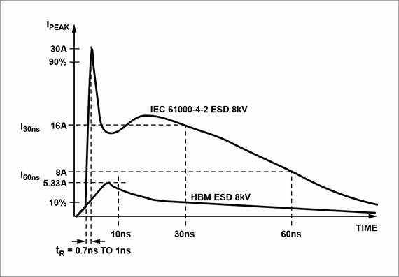
Also, even if there is a device compatible with HBM 8KV, it cannot satisfy 8KV of IEC 61000-4-2. As shown in the figure below (comparison of HBM and IEC models), since the energy given is completely different, there is a high possibility of destroying the device, so be careful.
Analog Devices products for system-level ESD
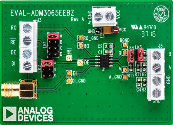
Analog Devices, Inc.'s (ADI) ADM3065E meets the IEC 61000-4-2 Level 3 standard without placing an ESD protection device on the bus line of the RS-485 interface. The ADM3065E ESD immunity is:
- IEC 61000-4-2 ≥ ±12 kV contact discharge
- IEC61000-4-2 ≥ ±12 kV air discharge
- HBM ≥ ±30 kV
The ADM3065E meets the IEC 61000-4-2 Level 3 standard without external protection elements, allowing for smaller PCB boards. It is most suitable as an interface device that realizes RS-485 communication for motor encoder boards.
Click here for recommended articles/materials
ESD Enhanced RS485 Device ADM3065E
EMC Surge Protection Level 4, Fully Tested RS-485 Transceiver ADM2795E
Click here to purchase products
ADM3065EARZ (A grade, SOIC)
ADM3065EBRZ (B grade, SOIC)
ADM3065EARMZ (A grade, MSOP)
ADM3065EBRMZ (B grade, MSOP)
EVAL-ADM3065EEBZ (Interface Development Tool, SOIC)
EVAL-ADM3065EEB1Z (Interface Development Tool, MSOP)