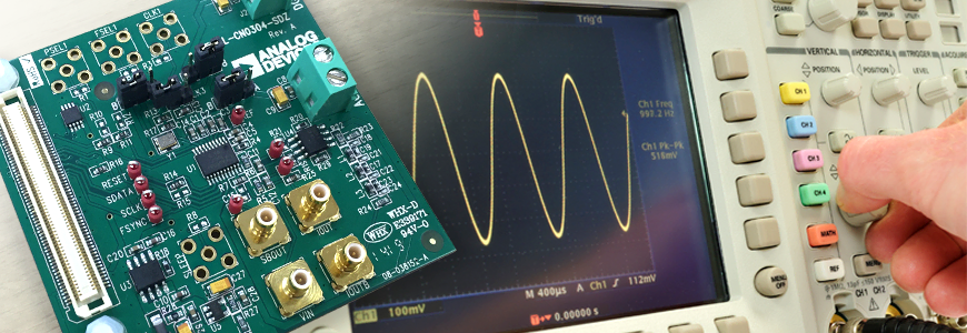
A spurious removal filter is required after the DDS
Last time, I explained that when using DDS, a filter circuit for spurious removal is required in the latter stage.
Direct digital synthesizer (DDS) that allows frequency changes in steps of several Hz Part 1
This time we will discuss the case of using a spurious removal filter. A kit for easy evaluation of the AD9834 is available: EVAL-CN0304-SDZ, so we will explain using this kit.
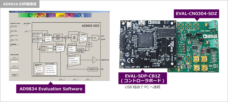
First, regarding the operating environment of the evaluation kit, the EVAL-CN0304-SDZ includes the EVAL-SDP-CB1Z (Eval Controller Board) required for connection with a PC and the GUI tool (AD9834 Evaluation Software) that is installed and used on the PC. Is required. By the way, EVAL-SDP-CB1Z can be connected to various evaluation kits, so some of you may already have one.
EVAL-CN0304-SDZの機能ブロック
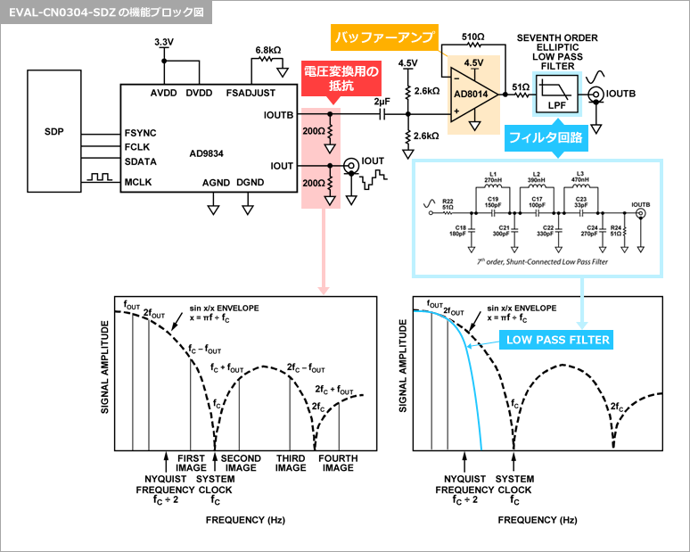
Now, let's take a closer look at EVAL-CN0304-SDZ. Please refer to the functional block diagram of EVAL-CN0304-SDZ.
First, the AD9834 output is a current output, so a voltage conversion resistor is connected.
Since a 6.8kΩ resistor is connected to the FSADJUST pin, a maximum current of about 3mA is output. Since a 200Ω resistor is connected to the output, a voltage of 0.6V will be obtained. As you can see in the figure, the IOUT terminal of the evaluation kit outputs the AD9834 output as is, so if you want to design your own filter, I think you should use this output.
On the other hand, the IOUTB terminal outputs the waveform that has passed through the buffer amplifier and filter circuit.
After AC coupling, the AD9834 output is input to the AD8014 with a DC bias applied to the midpoint of the input common mode voltage. A steep 7th order elliptic filter circuit is provided after the buffer amplifier, with a cutoff frequency of approximately 18MHz.
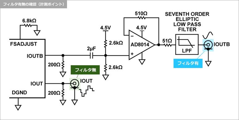
Actually compare the waveforms of filter circuit “with/without”
The measurement points are IOUT without filter and IOUTB after filtering. Connect an oscilloscope to each and observe the waveform.
計測結果
You can see that by passing the stepped waveform through the filter circuit, it becomes a beautiful sine wave.
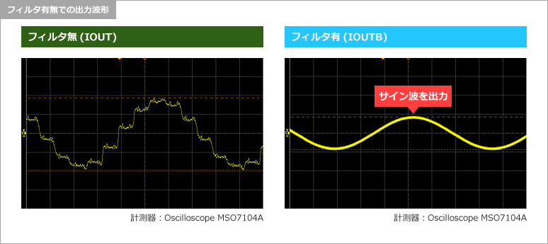
念のためスプリアスを確認してみます。オシロスコープのかわりにスペアナで観測、見事にスプリアスを除去できています。
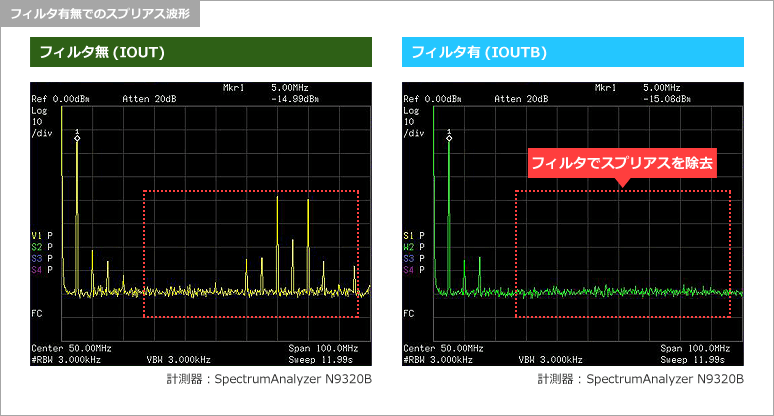
Therefore, a spurious removal filter is required after the DDS.
bonus
Some of you may have noticed that the amplitude after passing through the filter circuit is small, but when I checked it with a SPICE simulator, it appeared to be a 7th order elliptic filter.
Inquiry
If you have any questions regarding this article, please contact us below.
Analog Devices Manufacturer Information Top
If you want to return to Analog Devices Manufacturer Information Top, please click the button below.

