- Semiconductor BusinessHOME
- Products and Services of Macnica,Inc.
-
technical information

-
Events and Seminars
- Handling Manufacturer
- Support
- Inquiry
- Click here to purchase products
- Semiconductor business e-mail magazine registration
![]()
![]() Narrow down by specifying conditions
Narrow down by specifying conditions
現在2168件がヒットしています。check

What is a Direct Digital Synthesizer (DDS)?
DDS is a circuit that generates a signal waveform at any frequency from a reference clock. It may be easier to understand if we explain it as a technology that is also used in function generators.
I will not explain the operation of DDS, but as a circuit,
- phase accumulator
- 波形データが書き込まれたROM
- アナログ信号に変換するDAC
It consists of:
DDS has high frequency resolution, can easily output sine waves, and can instantly switch frequencies. On the other hand, it generates spurious signals, so a filter circuit is required in the downstream. DDS cannot generate frequencies higher than the reference clock. For this reason, if you want to generate a frequency higher than the reference clock, you need to combine it with a PLL in the downstream.
It is possible to realize a DDS circuit using an FPGA, but there are also products that consolidate all functions onto a single chip.

シンプルな構成のAD9834
In order to help you better understand DDS, I will use Analog Devices' AD9834, which has relatively simple functions, to explain it.
The AD9834 can generate sine/triangle waves with an output frequency of less than 37.5MHz at a reference clock of 75MHz. Typical applications include waveform generation, frequency phase tuning/modulation, low power RF/communication systems, liquid and gas flow measurement, sensor applications such as proximity, motion, and defect detection, test equipment, medical equipment, and a variety of other applications. It can be used for any purpose.
The configuration is shown below.

特長は?
The main features of the AD9834 are as follows:
High frequency resolution (frequency can be changed in increments of a few Hz)
The frequency resolution is greatly affected by the resolution of the phase accumulator. The AD9834 has a 28-bit phase accumulator, so the frequency resolution is MCLK/2^28.
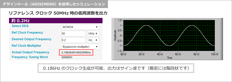
For example, if MCLK=50MHz, then 50MHz/2^28=0.1862...Hz, which is a resolution of approximately 0.2Hz.
Capable of generating low frequencies
DDS can generate waveforms with frequencies lower than the reference clock (actually, lower than the Nyquist frequency). Unlike the PLL method, DDS is a circuit suitable for generating low frequencies.
Frequency switching can be done instantly
The AD9834 has two frequency registers and two phase registers, which can be switched by pin settings. By using this function, FSK and PSK modulation can be easily performed.
Sine wave output possible
The waveform data ROM contains sine wave data, so it can output a sine wave. In addition to sine waves, the AD9834 can also output triangle waves and square waves (using the internal comparator).
ここでちょっと実験
Since DDS is capable of generating low frequencies, we will use Analog Devices' web-based design tool (ADISIMDDS) to simulate the output frequency and waveform.
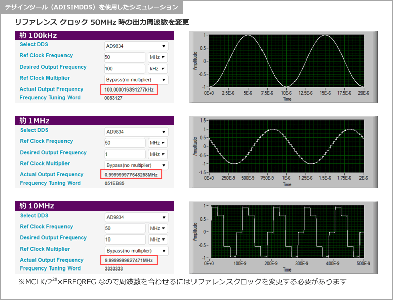
By the way, if you set the frequency to 100kHz, 1MHz, or 10MHz, the output waveform will become increasingly rough.
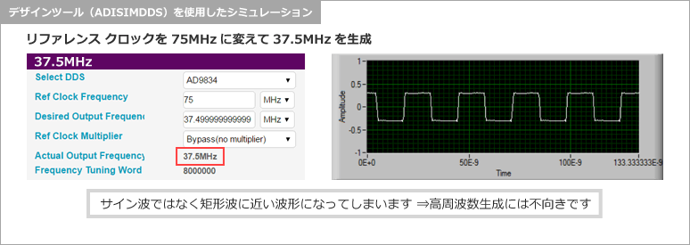
As an experiment, I set the frequency to the highest setting of 37.5MHz. It is more of a square wave than a sine wave.
DAC出力のためスプリアスが発生してしまう
Next, we will explain the issue of spurious emissions that occurs with DDS, as mentioned at the beginning.
As shown in the simulation results above, the DDS output has a stepped waveform. This is unavoidable since the output passes through a DAC, but it results in spurious signals.
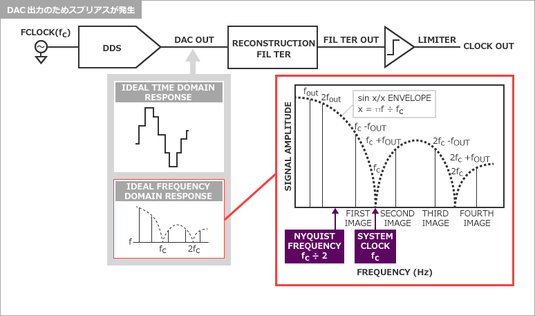
To be sure, we can use ADISIMDDS to simulate what kind of spurious signals will occur, so we will check this just in case.
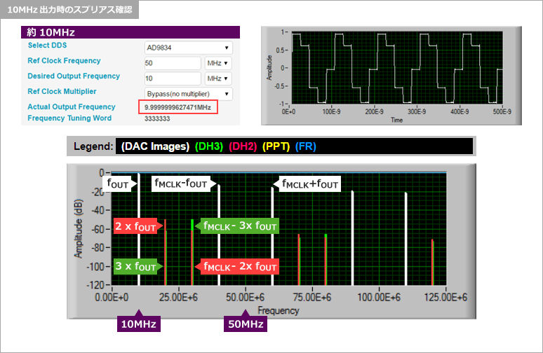
Since spurious signals are generated, a filter circuit to remove spurious signals is required after the DDS.
Next time, I will explain how to use a spurious removal filter.
Inquiry
If you have any questions regarding this article, please contact us below.
Analog Devices Manufacturer Information Top
If you want to return to Analog Devices Manufacturer Information Top, please click the button below.