- Semiconductor BusinessHOME
- Products and Services of Macnica,Inc.
-
technical information

-
Events and Seminars
- Handling Manufacturer
- Support
- Inquiry
- Click here to purchase products
- Semiconductor business e-mail magazine registration


 Narrow down by specifying conditions
現在2237件がヒットしています。check


Hello, I'm Mass Man.
In the previous column "Mass Man's FPGA Board Production 1", it was discovered that the overshoot of the clock signal exceeded the absolute maximum rated voltage value.
When I consulted with a senior employee, he advised me that overshoot could be suppressed by installing a damping resistor.
What is overshoot
An overshoot is a waveform distortion that protrudes upward at the rising edge of a square wave.
(Waveform disturbances protruding downward are called undershoots.)
Overshoot is caused by signal reflections and overlapping noise signals (Figure 1).

Figure 1. Causes of overshoot
Eliminate overshoot with damping resistor
If the overshoot becomes extremely large, it may damage the device receiving the signal, cause latch-up, or lower the reliability of the device, so proper care must be taken.
Overshoot can be suppressed by connecting a resistor (called a damping resistor) in series on the signal line.
My seniors taught me that it is appropriate to place the damping resistor near the output pin (Fig.2).

Figure 2. Location of damping resistor
The damping resistance value can be obtained by the following formula.
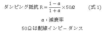
The damping resistor value that attenuates the overshoot voltage of 4.3 V to 3.3 V (attenuation rate a = 20 %) was found to be R = 33 Ω from (Equation 1).
I actually installed a 30 ohm resistor.
This is the state of the clock signal waveform before and after installing the damping resistance value (Fig. 3a, 3b).

Figure 3a. Clock waveform without damping resistor Figure 3b. Clock waveform with damping resistor
By placing a 30 Ω damping resistor close to the oscillator, we were able to suppress the overshoot voltage of the clock signal to 3.9 V.
what i learned
・Overshoot can destroy the device receiving the signal, cause a latch-up phenomenon, or reduce the reliability of the device.
・Overshoot can be suppressed by connecting a damping resistor in series to the near end of the signal line.