- Semiconductor BusinessHOME
- Products and Services of Macnica,Inc.
-
technical information

-
Events and Seminars
- Handling Manufacturer
- Support
- Inquiry
- Click here to purchase products
- Semiconductor business e-mail magazine registration


 Narrow down by specifying conditions
現在2247件がヒットしています。check


Here is a brief explanation of hazard signals that may confuse digital circuit designers, a simple mechanism of why they occur, and the effect that hazard signals have on a system.
See here for the impact on the system when asynchronous signals are input.
[Must-see for Beginners in RTL Design] Impact on the System when Inputting Asynchronous Signals
Read more about the difference between synchronous and asynchronous design here.
[A must-see for RTL design beginners] Differences between synchronous and asynchronous design
Things that bother digital circuit designers
Electrically normalized logic circuits have been built with a variety of implementations such as custom LSIs, standard cells, ASICs, FPGAs, CPLDs, and the old TTL. The concept is very simple because logic signals are normalized compared to analog signals. Its simplicity has greatly improved the current civilization. It is no exaggeration to say that the time has come when most physical phenomena in the natural world have been digitized and even computerized.
Among the many conveniences offered, at the stage of actually systematizing semiconductor circuits, macroscopic thinking can be normalized as a digital circuit (logic circuit), but microscopic It is essentially an analog signal. In particular, recent semiconductor devices have become faster, and logic circuits are no longer confined to the world of simple “1s” and “0s”. For example, high-speed transmission in the giga-hertz (GHz) band and weakening of handling signals for low power consumption can be mentioned.
In such a world that cannot be closed only by a simple “1” and “0” world, signals other than expected values, called “hazards” have been included in the original logic signals for a long time. People have been plagued many times.
What is a hazard signal
A hazard is a circuit malfunction that produces a value that differs from the normal value when one or more inputs change.
Hazard type
Hazards include dynamic hazards and static hazards.
- A dynamic hazard is a phenomenon that causes a transient value sequence to change three or more times when the output changes due to changes in one or more inputs.
For example, when transitioning from “1” to “0”: “1” → “0” → “1” → “0”. Also, when changing from “0” to “1”: “0” → “1” → “0” → “1”.
- A static hazard is when one or more inputs change, and the output, which should have the same value, temporarily takes a different value from the correct value. There are two cases of this static hazard.
1 Hazard: Error in which “1” output temporarily becomes “0”
0 Hazard: Error in which “0” output temporarily becomes “1”
Static hazard mechanism
This section describes static hazards.
The figure below shows a commonly used signal switching circuit (MUX).
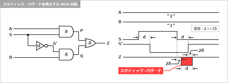
*In the example above, the delay (d) of the switching signal inverter is assumed to be much larger than the delay (δ) of the other AND-OR gates, in order to make the explanation easier to understand.
In this example, when inputs A and B are “1”, nothing should occur at the output even if the switching signal S is switched. If it is sufficiently large compared to the delay (δ) of , there will be a significant time lag between changes in signal S and changes in S'. In such a case, even if S changes from “1” to “0” and the p-point output becomes “0”, the S' signal has not yet become “1”, so as a result the q-point output is also “ remains 0”. Therefore, “0” is output at the final output Z point. This negative pulse (corresponding to delay d) is the static hazard. This hazard is caused by the mistiming of multiple signals. This timing gap is not uniquely determined (as will be described later), but is affected by various environments. Even if it doesn't occur at this moment, you never know when it will show up. Therefore, it is necessary to make a design that explicitly suppresses the cause of occurrence.
Suppression of static hazard signals
Static hazards occur when there is a time difference between the changes of two or more inputs. In other words, in order to eliminate static hazards, only one input should change. A common way to avoid static hazards is to add redundant circuitry. Use the Karnaugh map to find this suitable redundant circuit.
The lower left figure shows a Karnaugh map, and the lower right figure shows an example of adding a redundant circuit to the previous figure to suppress static hazards.
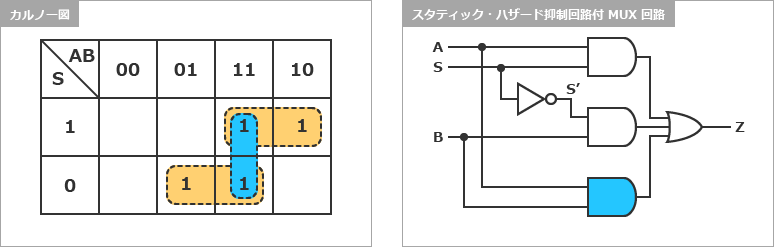
To make a Karnaugh map, write the input variables on the X and Y axes. As mentioned earlier, hazards do not occur when only one input changes, so in order to investigate this, arrange variables so that only one changes. In the above switching circuit (MUX), the variables are A, B, and S, so the two variables AB on the X axis are changed in 1 bit from 00 → 01 → 11. ” → “10” and S on the Y axis from “1” → “0”. Then fill the table with the output Z for each input. In this example, when the input switching signal S is “1”, when the input AB is “11” and “10”, and when S is “0”, AB is “01” and “11”. It will be when
In the upper left figure (Karnaugh map), the terms with two "1"s in a row in the column of the switching signal S are essential terms indicating the normal output terms AS and BS'. Now, among the input states where the output is “1”, if we look at the adjacent states where only one input value is different, if S is “1”, AS changes Z to “1” even if B changes. ” and S is “0”, no hazard occurs because BS' continues to define Z as “1” even if A changes. However, the change in S is not included in the normal term. This is what causes the hazard. Therefore, if we add the AB term (“11”), the AB term will continue to define Z to be “1” even when S changes, so we can eliminate the hazard. Since this term is not an essential term, it is deleted in general logic synthesis, but it is necessary from the viewpoint of preventing hazards. Therefore, when explicitly describing redundant functions in the source for the purpose of preventing hazards, it is necessary to set that part not to be logically compressed.
Effects of Hazard Signals on Systems
Normalized logic signals exist invisibly in implemented electronic circuits. This signal can be difficult to observe, even with instruments. In particular, it is impossible to observe with a logic analyzer used for observing logic circuits. Equipment for waveform observation such as an oscilloscope also needs to be quite expensive. In addition, wisdom and skill are required for hazard observation.
Unstable in the summer?
Especially bad is that devices tested in a favorable environment such as a laboratory or manufacturing factory (a stable power supply environment, an air-conditioned room, etc.) generally operate stably. The reason why I said "it works" is that in a blessed environment, the devil (hazard) doesn't come out in most cases. If a problem arises during the laboratory or factory testing stage, it can be addressed before it is shipped to the market. However, these demons (hazards) are spiteful, and they will immediately appear when they go to an environment where they are comfortable to live, such as unstable power supply or high/low temperature. Have you ever had the experience of "the device became unstable in the summer" or "the device became unstable when the production lot changed"? The main cause of this is Hazard.
Is the latest lot unstable?
This hazard is due to changes in device timing due to environmental changes. Especially in the world of FPGAs and CPLDs, the manufacturing process evolves rapidly even though they have the same type name. Other semiconductor logic devices generally use the same manufacturing process throughout their lifetime, but in the world of FPGAs and CPLDs, processes are miniaturized to improve yields and increase speed, which leads to device delays. tends to come earlier. As a result, there will be timing differences between the signals, which will induce hazards. In particular, for equipment that has a large lifetime lot and is repeatedly produced over many years, "the past production lot did not cause any problems," but "the latest lot is unstable." As a problem-solving approach that tends to fall into such cases, there is a case of not paying attention to the design review, saying, "There is no problem with the design because it worked normally in the past." In such cases, the problem-solving techniques may become ad hoc and cause the same problem later.
Causes of hazards and countermeasures
This timing deviation can also cause "hazards" due to fluctuations in the power supply voltage and changes in the operating temperature in the environment where the equipment is installed.
- Fluctuations in power supply voltage
- Ambient temperature fluctuation
- Manufacturing process change
The impact of hazards on the system is often immeasurable, but in order to solve these unstable factors on the system, the following methods including the "hazard deterrence measures" mentioned above should be adopted. is recommended.
- Hazard avoidance in register circuits by clock synchronization
- Output signal register latch output
- Hazard prevention measures with redundant circuits
At the end
In general, hazard phenomena cannot be detected in simulations or instruments in most cases. Therefore, it is important to consider that "circuits generated by electronic circuits always generate hazards" and to construct "circuits that are safe even if they occur". For that reason, synchronous design is an important point.
Click here for recommended articles/materials
[Must-See for RTL Design Beginners] The Difference Between Synchronous and Asynchronous Design
[Must-See for RTL Design Beginners] The Impact of Asynchronous Signal Input on a System
Regarding the operating characteristics of FPGA/CPLD