- Semiconductor BusinessHOME
- Products and Services of Macnica,Inc.
-
technical information

-
Events and Seminars
- Handling Manufacturer
- Support
- Inquiry
- Click here to purchase products
- Semiconductor business e-mail magazine registration
![]()
![]() Narrow down by specifying conditions
Narrow down by specifying conditions
There are currently 4342 results.
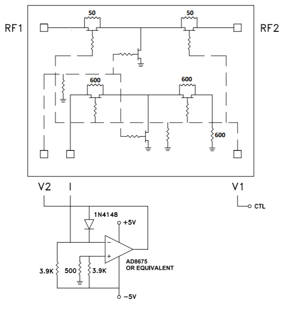
Analog Devices Attenuator : Please tell me the reference circuit diagram and control method when using HMC346AMS8GE.
RF and microwave
See the schematic on page 5 of the datasheet below. An external op amp circuit is required for impedance matching when varying the attenuation. Attenuation should be controlled by inputting 0V (minimum attenuation setting) to -5V (maximum attenuation setting) to V1.
![]() Experienced FAE
Experienced FAE
Free consultation is available.
From specific product specifications to parts selection, the Company FAE will answer your technical concerns free of charge. Please feel free to contact us.