- 半導体事業HOME
- マクニカの製品・サービス
-
技術情報

-
イベント・セミナー
- 取扱メーカー
- サポート
- お問い合わせ
- 製品購入はこちら
- 半導体事業のメルマガ登録
製品概要
Platform Manager 2は電圧/電流/温度の監視制御が統合的に可能なPower Managementデバイスです。Power Manager II [Pac-Power] で実施可能な電源シーケンス制御/電圧監視に加え、電流/温度の監視が可能です。また、Fault Logを残せることが大きな特徴であり、あらかじめトリガーを設定することで、電源異常やその兆候を検知し、各種監視信号を内蔵EEPROMへ記録することが可能です。
搭載しているハードウエアと機能
PLD
1280LUTのSRAM領域(及び内蔵コンフィグレーション用ROM)を有し、開発ツール上でGUIで任意のシーケンスをプログラマブルに作成可能です。また、GPIOを有しており、任意の信号をシーケンスに組み込むことが可能です。なお、余ったSRAM領域とGPIOは他FPGA同様、Verilog/VHDLで作成頂いたユーザーロジックを組み込むことができます。(電源制御部はサブ開発ツールPlatform Designer上でGUIで設計いただき、ユーザーロジックと共に設計開発ツールDiamond上で統合されます。)
Voltage Monitor Input
10chのアナログ電圧入力が可能です。各入力Portには電圧監視用コンパレーターが接続しています。コンパレーター出力をシーケンスへ組み込むことで、実電圧に基づいたシーケンス作成や、システム動作時の電圧異常監視を行う事が可能です。0V~5.75Vの監視が可能で、コンパレーターには最大368個のトリップポイントを設定可能であり、15-20mV単位の高分解能での監視設定が可能です。
また、1chあたり2個のコンパレーターを有し、ウィンドウでの監視が可能です。なお、規定範囲外電圧(負電圧含む)の監視も外部回路を設置することで可能であり、Lattice社HPに参考ドキュメントが掲載しています。
Fault Log
任意の監視信号をトリガー設定することで、システム異常/兆候を検知し、各種監視信号のコンパレーター出力値を内蔵EEPROM内に記録することが可能です。I2C Interfaceを介して記録をReadすることで、故障時などの各種解析に役立ちます。また、任意の外部SPI Flashへの記録もサポートしており、記録数を増やすことが可能です。
Current Monitor Input
2chの電流監視が可能です。電源供給回路中の数ミリΩsense抵抗の両端をPlatform Manager 2に接続する形になりますが、デバイスに増幅回路を内蔵し、ボード上に増幅回路を必要とせず、省スペースでの電流監視が可能です。
Temperature Monitor Input
2chの温度監視が可能です。ボード上などのThermal DiodeをPlatform Manager 2のPortに接続する形です。
Fan Control
システム内に冷却Fanを設置している場合、Platform Manager 2から出力するPWM信号をFanのドライバーなどへ入力することで、システム消費電力やボード温度に応じたFan回転制御を容易に行うことが可能です。サブ開発ツールPlatform Designer上で、GUI操作のみでFan回転用PWM信号の周波数/Dutyを設定可能です。また、Dutyは3種類の設定を持つことが可能で、上述Current/Temperature Monitor信号を含め、任意の信号で設定を切り替えることが可能です。
Open Drain Output
GPIOとは別に、10chの5VトレラントのOpen Drain出力Portを有します。DC/DCコンバーターのEnable Port等に入力することでシーケンス制御が可能です。加えて、4chの12VトレラントのOpen Drain出力Portを有し、MOSFETドライブも可能です。
ADC
10bit ADCを実装し、電圧/電流/温度の各入力値を外部からI2C Interfaceを介してRead可能です。
TRIM Control
4chのトリムアウトプットを有します。トリムポートを有するDC/DCコンバータへ接続することで、±1%以下の精度で出力電圧を安定させることが可能です。Platform Manager 2内で監視電圧をADCで読み取った上でフィードバックを行うため、安価なDC/DCをご使用しつつも温度下/経年による安定した出力が見込めます。また、出力値は1chあたり4セット保持可能なので、出荷検査における上下限検査にも使用可能です。
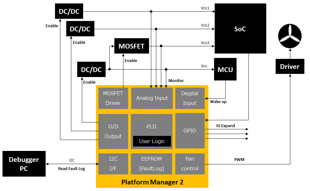
製品使用例
下図はあくまでも一例のため、実現可否については、本ページ下のお問い合わせボタンからお気軽にご連絡ください。
システム構成の一例です。電源シーケンスに加えてFault LogやFan Controlが可能です。
製品ラインナップ
|
Hardware Mangement Controller |
|
| パラメーター |
LPTM21 |
| Voltage Monitioring Inputs |
10 |
| Current Monitioring Inputs |
2 |
| Temperature Monitioring Inputs |
2 |
| Number of Trimmiing Channels |
4 |
| MOSFET Drives |
4 |
| On-Chip Non-Volatile Fault Log |
✔ |
| Number of LUTs |
1280 |
| Distributed RAM(kbits) |
10 |
| EBR SRAM(kbits) |
64 |
| Number of EBR Blocks(9 kbits) |
7 |
| User Flash Memory(kbits) |
64 |
| Number of PLLs |
1 |
| Communication I / F |
I2C / SPI / JTAG |
| Programming Interface |
I2C / SPI / JTAG |
| Operationg Voltage |
2.8 V to 12 V |
| 237-Ball ftBGA(1mm)(17 x 17) |
106(Digital Input本数) |
EBRはEmbedded Block RAMの略
評価ボード
評価ボードの詳細、購入をご検討の方は、以下購入ボタンから問い合わせください。
お問い合わせ / お見積もり
本製品に関してご質問、見積もりなどの希望がありましたら以下より問い合わせください。