- 半導体事業HOME
- マクニカの製品・サービス
-
技術情報

-
イベント・セミナー
- 取扱メーカー
- サポート
- お問い合わせ
- 製品購入はこちら
- 半導体事業のメルマガ登録
![]()
![]() 条件を指定して絞り込む
条件を指定して絞り込む
現在2178件がヒットしています。check

第1話「技適を取ろう」では、技適がなぜ必要で、どこで認証を受けるかという事をご紹介させていただきました。しかしながら、技適を取得するためには、試験をするためのソフトウェアや取得対象となる無線設備に関する書類など、多くの物を準備する必要があります。
準備する物を大まかに分類すると以下の3点に分けられます。
- 申請対象となる無線設備の設計情報等の資料
- 申請するアンテナの仕様
- 試験をするためのソフトウェアとハードウェア
今回は、申請対象となる無線設備の設計情報等の資料と、申請するアンテナの仕様をどのように準備したかをご説明いたします。
※試験をするためのソフトウェアとハードウェアについては、第3話で紹介します。
技術基準適合証明取得までの道のり 第1話「技適を取ろう」
技術基準適合証明取得までの道のり 第2話「書類の準備」
技術基準適合証明取得までの道のり 第3話「試験実施」
技適の申請に必要な書類を準備しよう
技適を申請するためには多くの資料が必要となります。例えば、申請内容を記載する申請書を始め、無線設備のブロック図や配置図等の資料を準備しなければなりません。
今回初めて技適を取得する私たちは、右も左も分からない状況でしたが、テュフ ラインランド ジャパン株式会社 様のサポートをいただきながら、必要となる書類を全て準備することが出来ました。以下が最低限必要となる書類の一覧です。
| No. | 資 料 | No. | 資 料 |
| 1 | 申請書 | 6 | 容易に開けられない構造であることの説明資料 |
| 2 | 無線設備系統図(ブロック図) | 7 | アンテナのデータシート |
| 3 | 工事設計書 | 8 | ラベル配置図 |
| 4 | 部品配置図 | 9 | シリアルナンバーリスト |
| 5 | 概観図 | 10 | 主要なICのデータシート |
少しだけ準備した資料をご紹介します。
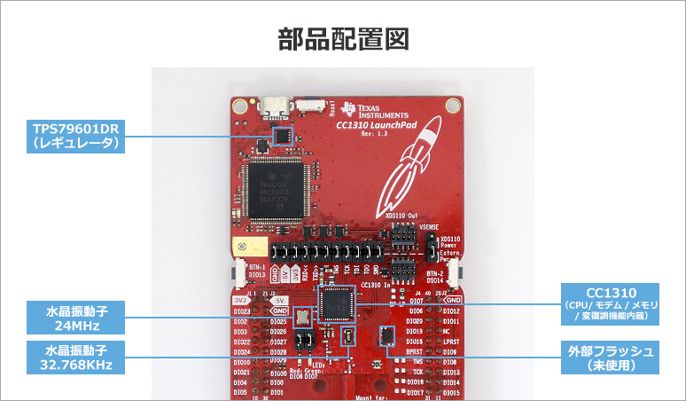
部品配置図
部品配置図は、水晶振動子やメモリ、CPUといった主要な部品の写真が求められたため、以下の資料を用意しました。このように、どんな物がボードのどこに配置されているか説明する資料です。
ラベル配置図
今回は無線設備1台1台に対して個別に性能を証明する「技術基準適合証明」を申請するため、認証後にテュフ ラインランド ジャパン株式会社 様にてラベルを無線設備に貼付していただく必要があります。そのため、ラベルの貼り付け位置を指定するラベル配置図という資料を準備しました。
下記の図で貼っているラベルは、事前にテュフ ラインランド ジャパン株式会社 様からサンプルラベルを入手し貼りました。
なお、仮に工事設計認証を取得される場合は、認証取得者がラベルを準備して貼る必要があるため、ラベル図およびラベル配置図が提出書類として必要です。
アンテナのデータシートは申請者自身で用意する必要あり
無線製品においてアンテナは切っても切れない要素の1つです。そのため、技適を取得する場合においても、申請するアンテナの利得や放射パターンといった情報が必要です。また、申請するアンテナ全てに対するこれらの情報を入手する必要があります。
アンテナは何種類でも申請することが可能です。今回はアンテナの特性などの違いを確認する為に、全部で4種類のアンテナを申請することにしました。
TI社から4種のアンテナを申請
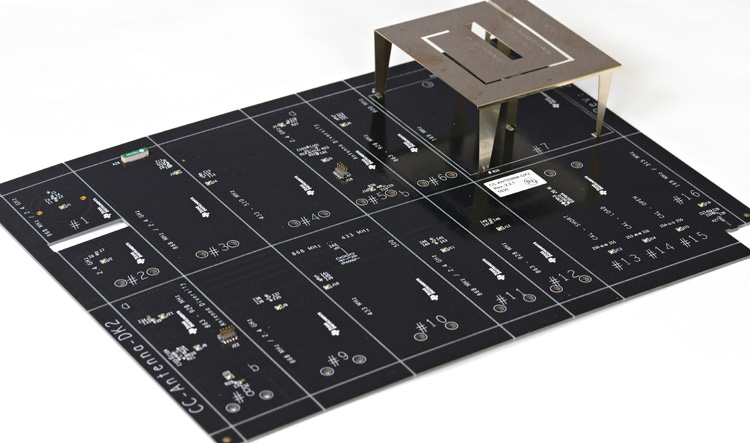
技適を取得したLAUNCHXL-CC1310上のパターンアンテナとTexas Instruments社(以下、TI社と記載)からリリースされているアンテナキット(CC-ANTENNA-DK2)から合わせて4種類を申請しました。
ちなみにこのCC-ANTENNA-DK2は、PCB アンテナ、ヘリカル・アンテナ、チップ・アンテナ、868/915MHz と 2.4GHz を組み合わせたデュアル・バンド・アンテナを含め 16 個のアンテナが付属しており、169MHz から 2.4GHz の周波数に対応しています。
申請するアンテナは決まったけれども問題が…
申請するアンテナが決まったので後は書類を準備するだけでしたが、ここで1つ問題が発生してしまいました。
技適を取得する周波数での利得や放射パターンの情報が必要となるのですが、採用したアンテナに対するそれらの書類がTI社から提供されていませんでした。
そのため、アンテナの特性を測るサービスを行われているSGSジャパン株式会社様に、不足しているアンテナの特性情報の取得を依頼いたしました。
SGSジャパンでアンテナ特性情報を入手!
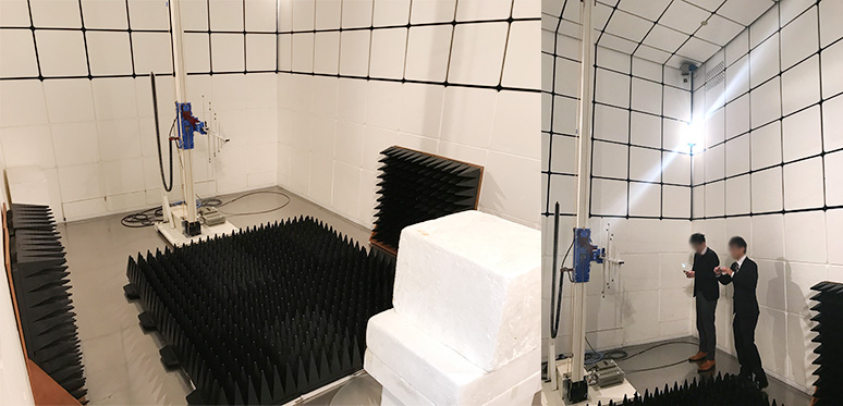
SGSジャパン株式会社様の横浜試験所にてアンテナ特性試験を行っていただきました。
写真はアンテナの特性を測定した場所である、SGSジャパン株式会社様の横浜試験所の電波暗室です。左側の写真の手前に写っている発砲スチロールにアンテナを設置し測定を実施しました。以下の写真をご覧いただくとわかると思いますが、この電波暗室はかなり広いところでした。
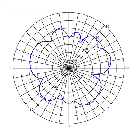
周波数やXYZ座標などを切り替えながら、アンテナの利得や放射パターンを測定いただき、結果として以下の写真のような電波放射パターン図など、申請に必要となるアンテナの特性情報を入手することが出来ました。
最終話では技適の試験を行います!
これで技適の申請に必要となる書類が一通り揃いました。
次回、第3話「試験実施」では、試験をするために準備したハードウェアとソフトウェア、テュフ ラインランド ジャパン株式会社 様での試験の様子をお届けします!
お問い合わせはこちら
本記事でご紹介したTI社の開発キットや、Sub-GHz対応製品に関する詳細な情報をお求めの方は、是非こちらからお問い合わせください。


関連情報
おすすめ記事/資料はこちら
技術基準適合証明取得までの道のり 第1話「技適を取ろう」
技術基準適合証明取得までの道のり 第2話「書類の準備」
技術基準適合証明取得までの道のり 第3話「試験実施」
Sub-GHz帯無線通信の飛距離を測定してみた 前編「まずはやってみよう」
Sub-GHz帯無線通信の飛距離を測定してみた 後編「改良して2kmに挑戦」