![]()
![]() Narrow down by specifying conditions
Narrow down by specifying conditions
現在1888件がヒットしています。check

This article describes the main points of Taoglas' GPS patch antenna application note: APN-12-8-002.B. For details, please refer to the application note at the following URL.
Advantages and points of use of GPS Patch Antenna
Basic product information
GNSS (Global Navigation Satellite System) refers to the global positioning satellite system in Japanese.
In general, American GPS/Russian GLONASS/China's Beidou/Europe's Galileo can be mentioned, and Japan's "MICHIBIKI" is QZSS (quasi-zenith Satellite System), a supplementary/reinforcement system for GPS centered on Asia and Oceania. is positioned as
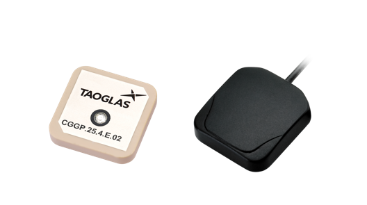
In this article, we will describe the GPS patch antenna, which is a familiar part of GNSS.
Basics of Patch Antennas
Taoglas GPS patch antennas are small and can be used for compact applications. This is because it can maintain high gain in the zenith direction, which is important for satellite navigation systems (GNSS).
It is also circularly polarized and can efficiently receive circularly polarized signals from GPS satellites.
Arrangement
The ideal location for a theoretical GPS antenna is in the center of the PCB and on top of the GPS receiver.
There are reasons for this, both in terms of electricity and physics. Electrically speaking, the input to the GPS receiver and the antenna feed point are directly above the GPS receiver, eliminating the need for transmission lines. The physical implication is that if the antenna is centered, placing it near the edge of the PCB will not distort the radiation plot.
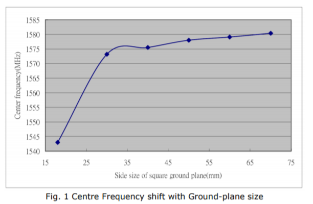
Effect of GND plane
The larger the GND plane, the greater the antenna gain in general.
Also, the center frequency of the antenna changes with the size of the GND plane.
(The figure below is an example.)
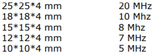
bandwidth
The effective bandwidth of a GPS antenna is typically measured in a frequency band with return loss less than -10dB. The bandwidth of the ceramic patch GPS antenna varies with size.
Therefore, the smaller the antenna, the more likely the device will experience a frequency shift. Using the antenna in this state is not optimal, so the antenna bandwidth should be readjusted to ensure an effective bandwidth at 1.5754 GHz for GPS.
Below are the reference values for the characteristics.
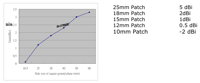
GAIN
Antenna gain is determined by directivity and surface area. The GPS antenna rises toward the zenith and gradually lowers horizontally. The relationship between GND plane and peak gain is as follows.
(You can see that the peak gain increases as the GND plane increases.)
Advantages of GPS patch antenna
・Suitable for applications where accuracy is important
・Reduced mounting man-hours
・Economical (low cost)
・Compact
・Adjustable to the optimum value according to the environment
Implementation
There are two mounting methods for the GPS patch antenna.
■Pin mounting type products
Mount it on the board with double-sided tape in the usual way. The pins are routed through the backside of the board and soldered to the feed points.
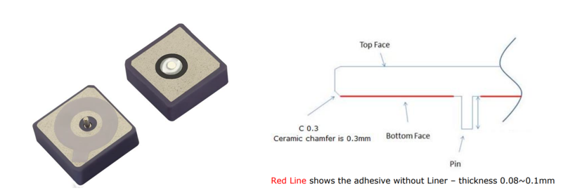
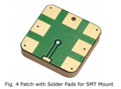
■ SMD type products
There are also unique antennas that can be surface mounted. Supplied on tape and reel, it can be soldered directly to the pads with normal reflow. The maximum reflow temperature is 261°C/41 seconds. It is also very resistant to vibration.
environment
All antennas are electrically affected by proximity to components, housings, etc. The center frequency is shifted and the radiation pattern is also distorted. This causes center frequency and impedance tuning.
A maximum of 4-10mm clearance in all directions from the board or housing is required for maximum efficiency.
tuning
A GPS patch antenna must be aligned with the ground plane in which it is mounted to account for frequency shiftsfrom the environment in which the antenna is placed.
This is faster and more accurate to evaluate in practice than using simulation tools.
■ Impedance matching
The antenna is tuned to approach 50Ω on the Smith chart. The industry standard for return loss (S11) in the occupied bandwidth is less than 10dB. However, the most important thing is to check the radiation characteristics/gain/occupied bandwidth in the usage environment.
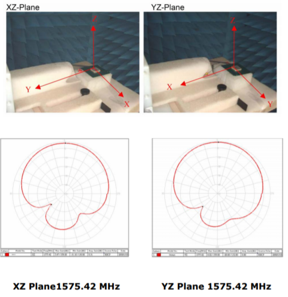
■ Radiation pattern and gain test
The radiation characteristics in the XY and YZ planes of the antenna are obtained with the device. A horizontal radiation pattern can be generated by taking data at 0/180 degrees where they intersect and drawing a horizontal line with four reference points. This allows you to obtain the 3D pattern of radiation.
(The actual 3D pattern is described in each data sheet, and is omitted in this article.)
These radiation pattern characteristics provide some important information such as performance comparisons with other antennas and the antenna's ability to receive signals from low-altitude satellites in operation. The pattern below was obtained using a 25mm*25mm*2mm patch antenna on a 35mm GND plane.
https://cdn3.taoglas.com/datasheets/SGGP.25.2.A.02.pdf
Related seminar information
This seminar is recommended for those who want to know the basics of GNSS and market trends. If you are interested, please apply from the page below.
Inquiry
If you have any questions about this product, please contact us from the following.
Back to Taoglas Manufacturer Information Top
If you want to return to Taoglas manufacturer information top page, please click below.