![]()
![]() Narrow down by specifying conditions
Narrow down by specifying conditions
現在1888件がヒットしています。check
![[Application Note] Flexible PCB Antenna Edition](/business/semiconductor/articles/articles_taoglas_134638_cover_2.png)
For this article, Taoglas Flexible PCB Antenna Application Note: APN-11-8-004.C explains the advantages and usage points of flexible PCB antennas. For details, please refer to the application note at the following URL.
https://www.taoglas.com/wp-content/uploads/pdf/APN-11-8-004.C.pdf
Advantages and usage points of flexible PCB antennas
Basic product information
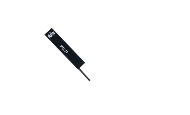
Flexible PCB antennas are flexible, thin, and highly reliable, and are widely used in the wireless industry. Polyimide is used for the substrate to obtain antenna characteristics. This makes it possible to manufacture various monopole antennas, dipole antennas and F antennas.
size
In general, the larger the surface area of the antenna, the higher the gain and radiation characteristics. The table below shows the difference in VSWR and radioactivity characteristics due to the difference in surface area.
small surface area
|
CLRMore |
GSM |
PCS |
DCS |
|
| band |
824 - 896 |
880 - 960 |
1850-1990 |
1710-1880 |
| VSWR |
4.76 |
2.2 |
2.28 |
1.89 |
| Min.Return Loss dB |
-3.71 |
-8.49 |
-8.18 |
-10.17 |
* PCB antenna data for surface recognition
large surface area
|
CLRMore |
GSM |
PCS |
DCS |
|
| band |
824 - 896 |
880-960 |
1850-1990 |
1710-1880 |
| VSWR |
1.92 |
1.65 |
1.4 |
1.92 |
| Min.Return Loss dB |
-10 |
-12.24 |
-15.55 |
-10.01 |
* PCB antenna data for surface recognition
Assumed application
The flexible PCB antenna is built into the product housing and is suitable for small applications where sufficient space and size for mounting the antenna cannot be secured. The mounting method is to attach to the plastic housing with double-sided tape. (Refer to Topic: Effect of GND plane)
shape and thickness
The flexible PCB antenna is ultra-thin at only 0.5mm, making it easy to install on your product.
Effect of GND plane
If the distance between the antenna and the GND plane is not sufficient, the radiation efficiency and radiation pattern may decrease. Because the signal is confined by the GND plane. So it is generally recommended to have 20mm clearance from the metal in all directions to ensure good antenna radiation efficiency.
impedance
The F circuit should be designed with 50Ω on the equipment side, transmission line, and load side.
bandwidth
Taoglas PCB antennas typically have a return loss of -7.5dB or less in the application band of interest (e.g. 850/900/1800/1900 for GSM). Regarding the return loss, the bandwidth is defined as the point where the return loss is -10dB or less, and -5dB is attenuated.
VSWR (Voltage Standing Wave Ratio)
VSWR (Voltage Standing Wave) is a function of return loss and represents the reflected power from the antenna. A lower VSWR means a better transmission match with the antenna, and more power is delivered to the antenna. VSWR=1 is the ideal condition with no reflection. The target is VSWR=1.5, but in reality, VSWR=3 or less can cover the severe environment of multi-band antennas.
GAIN
A 20mm clearance is recommended for best gain and radiation efficiency.
efficiency
Antenna efficiency is the ratio of the total power fed into the antenna to the power radiated by the antenna. Efficiency is a good overall measure of omnidirectional antennas for mobile communication systems such as GSM (Global System for Mobile Communications) and WLAN (Wireless LAN). High efficiency (30%-50%+) can be achieved if the PCB antenna has enough surface area.
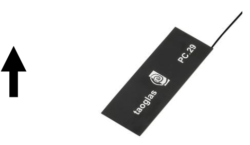
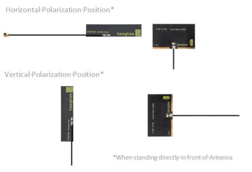
polarization
Polarization indicates the direction of an oscillating wave. All Taoglas cellular and broadband antennas are capable of very efficiently combining broadcast signals from linearly polarized antennas mounted on cellular base stations. Depending on how the antenna is installed, it can be horizontally or vertically polarized.
Advantages of Flexible Antenna with Cable
・Can be directly attached to a plastic housing
・Main board space can be reduced
・Very inconspicuous
・Flexible customization of size, shape, cable, connector, etc.
・Easily supports multi-band frequencies
Mounting
Taoglas' flexible PCB antenna uses [3M-467] double-sided tape for high reliability. Orientation of the antenna is generally not important as long as there is sufficient clearance from the metal.
About the Environment
All antennas have an impact on electrical performance when placed close to the device or enclosure. If placed in an enclosed area, it should be spaced 20mm from metal such as GND and other devices for maximum efficiency. If these clearances cannot be secured, the antenna efficiency will decrease and the tuned frequency will shift. Proximity effects also adversely affect the antenna radiation pattern. Never use metal or metallic materials for the housing when using the internal antenna.
Taoglas' flexible antenna is designed to be placed on 2-3mm ABS plastic. Other housing materials and thicknesses may shift the tuning frequency slightly. Also, some colorants, such as carbon black, can significantly degrade antenna performance due to their RF absorbing properties. We also do not recommend using hygroscopic materials such as nylon.
tuning
The frequency characteristics of the flexible PCB antenna can easily change even if the cable is bent more than 30 degrees when the device is closed.
isolation
It is a coupling characteristic between two antennas that is different from isolation. For example, for CDMA diversity antennas, the ideal target for the main and auxiliary antennas is -10dB. Also, do not let the antenna cable get close to or cross other antennas.
Cable & Connector
A 1.13mm diameter micro coaxial cable is suitable for most cellular antennas. If the cable length is less than 150mm, cable loss is not a big factor. The cable should have a good GND. Route the cable as close to device GND as possible.Also, do not form loops in the cable. Because it creates a magnetic field that causes a frequency shift and interacts with the magnetic field of the main antenna. Therefore, please keep the cable away from emitting parts such as LED drivers, CPU, chips, etc.
Inquiry
If you have any questions about this product, please contact us from the following.
Back to Taoglas Manufacturer Information Top
If you want to return to Taoglas manufacturer information top page, please click below.