- Semiconductor BusinessHOME
- Products and Services of Macnica,Inc.
-
technical information

-
Events and Seminars
- Handling Manufacturer
- Support
- Inquiry
- Click here to purchase products
- Semiconductor business e-mail magazine registration
![]()
![]() Narrow down by specifying conditions
Narrow down by specifying conditions
現在2183件がヒットしています。check
Digital isolator and photocoupler technology
Features of Digital Isolator
Compared to optocouplers, digital isolators have advantages such as size, speed, stability, power consumption, easy-to-use specification definitions, and reliability, and can be used in a variety of applications. Below are some details.
・High reliability
Applications such as HEV/EV and wind energy systems are used in harsh environments.
In such applications, the isolator must have a lifetime of 20 years or more in a high temperature environment exceeding 120°C.
Isolators are also rated for long-term reliability.
・High CMTI
There are environments where common mode changes are severe, such as driving power devices that operate at high speed and environments with a lot of noise.
Devices with high CMTI (Common-Mode Transient Immunity) characteristics for such environments are required.
There are many isolator products with high CMTI.
・Low EMI, immunity to high electric and magnetic fields
EMI causes data errors, especially in medical applications with low amplitude signals such as electrocardiographs.
In order to maintain high performance, insulating devices with characteristics that can eliminate external electric and magnetic field interference are important.
The isolator has low EMI and high immunity to magnetic and electric fields.
・Definition of easy-to-design specifications
Photocouplers have large temperature characteristics and changes over time, so it is necessary to consider various characteristics when designing.
Digital isolators, on the other hand, have defined specifications including temperature characteristics and changes over time.
It is possible to predict characteristics, including changes over time, to some extent, making it easy to design with high reliability.
Driving high-speed power devices requires severe design, such as design with strict timing specifications. There are many considerations such as device variation, temperature, current, as well as device aging. The photocoupler design margins, which have large variations in characteristics, are cut and the characteristics deteriorate.
In this way, digital isolators are obviously easier to design than photocouplers.
Timing Variation vs. Temperature
The delay time of the photocoupler is easily affected by temperature and other factors even if the input signal is the same. Here is an example of timing variations due to temperature.
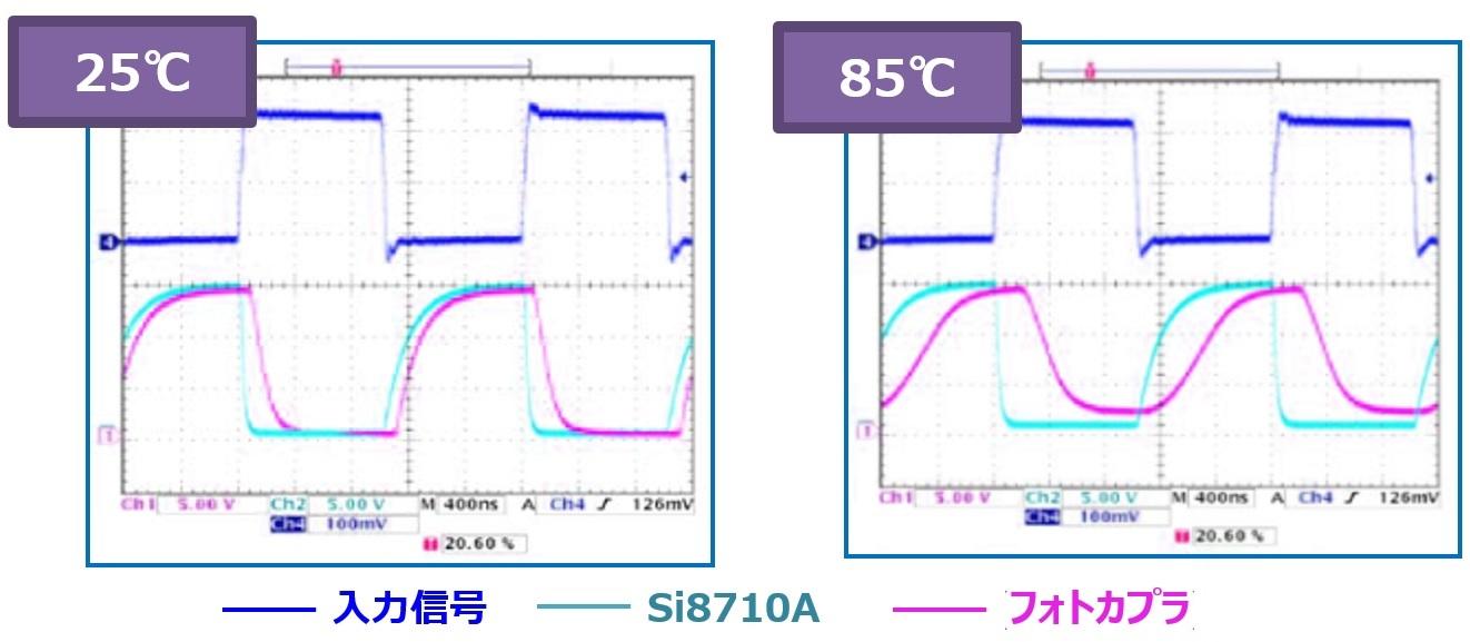
The figure compares the characteristics of the Si8710A with the same open collector output for the same input signal. The digital isolator uses Si8710A (LED input, open collector output). When the temperature rises, the photocoupler's delay time and rise/fall characteristics change significantly, but the change in the digital isolator is almost unchanged. Digital isolators have extremely small variations between elements compared to photocouplers.
Delay time Pulse width distortion temperature characteristics
Here we show the detailed differences in characteristics regarding the delay time. The graph below compares the stability of propagation delay and pulse width distortion with respect to temperature characteristics for the HCPL-2400 (20 Mbps) photocoupler and the Si8660Bx (10 Mbps) CMOS digital isolator, which have high-speed characteristics.
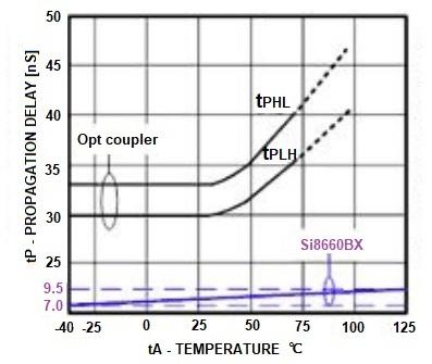
Figure Propagation Delay vs. Temperature Characteristics
It shows the temperature characteristic dependence of propagation delay.
The characteristics of the photocoupler do not match at rising and falling.
It must be designed to satisfy the slower one.
As the temperature increases, the propagation delay becomes slower.

Figure Pulse Width Distortion (PWD) vs. Temperature Characteristics
PWD (Pulse Width Distortion) Pulse Width Distortion is the difference between Hi to Low propagation delay and Low to Hi propagation delay.
This may change the duty ratio of the signal.
Some photocouplers deteriorate significantly when the temperature rises.
Effect of Input Current on Delay Time
Photocouplers are affected by the amount of input current and delay characteristics. It shows the effect of input current and external delay time on the HCPL-2400 optocoupler as described in the manufacturer's application note.

Figure Photocoupler/CMOS isolator propagation delay vs. temperature characteristics
Optocouplers behave differently with and without a "peaking" capacitor (Cp) that momentarily increases the LED current during turn-on and turn-off to improve response. Also, the rise/fall times (tPHL and tPLH) are not symmetrical and should be examined separately. Propagation delays for CMOS digital isolators are shown at the bottom of the graph as Si86xx characteristic curves. It is flat in the temperature range of -40 to +125°C.
Summary
Compared to photocouplers, digital isolators can achieve high-speed data rates and low delays, exhibit little characteristic change due to temperature changes, and offer high added value in terms of timing design.
It offers improved performance, reliability and ease of use, making it ideal for system component installations and new designs.
Isolator product page
Here is a digital isolator product page with useful features.
Inquiry
If you have any questions regarding this article, please contact us below.
To Sky Works Manufacturer Information Top
If you want to return to Skyworks' manufacturer information top page, please click below.