
![]()
![]() Narrow down by specifying conditions
Narrow down by specifying conditions
現在1888件がヒットしています。check

It's all about balance, and that makes decisions difficult. If money is involved, it's a different story. How long can it be collected? What is the value of reducing CO2 emissions? What is the effect of reducing CO2 emissions? While the determinants may be subjective and dynamic, it would be nice to be a little more scientific when choosing semiconductors for EV power converter design.
Even if you choose wisely and decide to use Qorvo's wide bandgap SiC FETs, there are still trade-offs to consider. Examples include number and rating of paralleled devices, switching frequency, mode of operation, efficiency goals, allowable junction temperature rise, distribution of conduction and switching losses, and cost. Device selection is constrained by external conditions. For example, a 3.6kW totem-pole power factor correction stage used in electric vehicle chargers typically produces a voltage of 400V, operates at 60kHz, and has an inductor ripple current of about 20% in continuous conduction mode. Become. Given these conditions, using a 750V SiC FET for the 'fast' leg is a good choice with low loss and available up to 6mΩ on-resistance. But in reality, cost is always an issue.
Therefore, it is necessary to consider whether lower cost components can be used at the expense of some loss. Qorvo makes it easy to assess this problem using the 'FET-JET Calculator'. You can choose from a wide range of power conversion topologies and operating conditions, and calculate switching and conduction losses and temperature rise for various devices. You can select the number of components connected in parallel and specify the performance of the heatsink.
To offer the widest selection, Qorvo expands its 4th generation 750V devices to offer a total of 8 on-resistances ranging from 6 to 60mΩ. Calculations with the FET-JET calculator under certain conditions yield plots like the one below, giving interesting results.
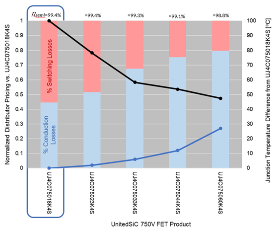
No efficiency loss is seen when changing from 18mΩ device (UJ4C075018K4S) to 23mΩ device (UJ4C075023K4S). This is due to the reduced switching losses, although the conduction losses have increased. But the device costs about 20% less. A 33mΩ device (UJ4C075033K4S) is 0.1% less efficient and consumes 36W more power, but the switch cost can be reduced by more than 40%. The junction temperature rises about 6°C with the same heatsink, but still stays at about 102°C. A 60mΩ device (UJ4C075060K4S) is less than half the cost of the best SiC FETs considered, albeit at the penalty of 22W extra dissipation and 122°C junction temperature. Given the cost trade-offs of device type and temperature rise, improved heatsinks can be considered, but the added size and weight are penalties for EV applications.
In addition, if two 60mΩ types are arranged in parallel, the total resistance value will be halved and the switching loss will increase, but the overall thermal resistance will decrease, so the rise in junction temperature will be suppressed and the temperature dependency will be reduced. Another option is to suppress the increase in on-resistance. The FET-JET Calculator allows you to experiment with multiple devices with different on-resistance levels and heatsink options. A tipping point may be found where the combination of the lowest-loss device and the highest-cost device can reduce the heatsink to a level where, for example, water cooling can be eliminated, far outweighing the additional cost of the switch.
Inquiry
If you have any questions regarding this article, please contact us below.
Qorvo manufacturer information top page
If you want to return to Qorvo manufacturer information top page, please click below.
