
![]()
![]() Narrow down by specifying conditions
Narrow down by specifying conditions
現在1887件がヒットしています。check

Overview
Devices built with materials that exhibit wide bandgap, such as silicon carbide (SiC), combine low conduction and switching losses, high operating junction temperatures, and fast switching speeds to create transistors that can sustain high power densities. provide to These high power densities are attractive for enabling smaller power control and conversion circuits, but cannot be achieved by semiconductor material selection alone. Such devices should be offered in low thermal resistance packages such as TO-247. This allows the heat dissipated by the device to easily escape. Unfortunately, TO-247 packages often have high inductance connections that can limit switching speed.
This article provides a solution to the inductance problem using a technique called Kelvin connection.
What is a Kelvin connection
The Scottish/Irish experimentalist Lord Kelvin was interested in the accuracy with which physical phenomena such as electric currents could be measured. He uses Ohm's law to measure low resistance by checking the voltage drop that occurs when a defined current is applied, so that the voltage is accurately measured in a system separate from the one carrying the current. I understand that I need to take measurements. This method became known as the Kelvin connection.
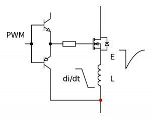
Kelvin connections were originally intended to measure static voltages at good points in a circuit, but they can also be used to inject voltages at good points. For example, when driving the gate of a MOSFET switching at high frequency, the source terminal of the device is the common connection point for the gate drive voltage and the drain-source current. If there is an inductance L in the source connection (Figure 1), changes in current will affect the gate voltage in proportion to the inductance L and the rate of change of the current. When the gate is driven off, the voltage developed across the inductance L tends to hold the gate longer, slowing the current drop. Conversely, during turn-on, the voltage across inductor L acts to slow the rate of rise of the current.
Managing the effects of lead inductance
The inductance L is due to the internal bond wires of the MOSFET and is typically around 1nH per mm. If the device has leads like the TO-247 package, these external connections will also increase L.
When switching times were measured in microseconds, amperes of switching current produced only millivolt transients while the gate drive voltage changed very little. However, wide bandgap (WBG) devices can switch tens of amperes in a few nanoseconds, producing transients of about 2 to 5 V per nH of connection inductance. When this transient is added to the gate drive, the MOSFET stops switching off, ringing and even risking device failure.
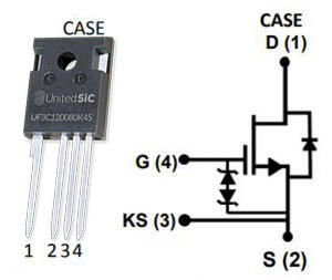
For Si MOSFETs, driving the gate to a negative voltage (perhaps up to -10V) when off will prevent voltage spikes from degrading the bias. This results in higher gate drive power dissipation, which also increases proportionally to the total gate drive voltage swing. This problem is exacerbated for WBG devices based on SiC and gallium nitride, which can only support negative drive voltages of about -3V. The solution is to make a Kelvin connection so that the gate drive return is as close as possible to the source connection of the MOSFET die. This is easy with chip-scale packages, but if you want to use the TO-247 package with its superior thermal properties, you'll need to add a fourth lead to make the Kelvin connection (Figure 2).
Faster switching improves efficiency
Using a Kelvin connection to control lead inductance and potential effects on gate bias means operating wide bandgap devices at their native switching speed without applying a negative gate voltage. . This simplifies the drive circuitry. This effect is dramatic. When Qorvo's SiC JFET cascode is placed in a 3-terminal package, the device must be slowed down to maintain reliability. When implemented in a Kelvin-connected 4-terminal package, the current slew rate can exceed 5000A/µs, enabling higher efficiency without affecting gate drive signals.
Physically, even with a TO-247 package, the lead inductance of the device must be considered, but a small snubber is usually placed across the drain to source to stop voltage overshoot in the power path. The gate drive loop should also be laid out carefully to minimize inductance and prevent pickup from external magnetic fields by the main rectification loop.
*For Qorvo's SiC JFET cascode, please refer to the following URL.
What is a Kelvin connection?
There are other practical issues with implementing Kelvin connections. If the gate drive return is the main system 0V and is connected to power ground, it would probably be inconvenient to make this common connection point a Kelvin connection to the switch. If the power circuit is a full bridge, there are at least two low side devices, each Kelvin connected, so which one should be connected to the system 0 V? If the Kelvin connection is 0V for the system, the voltage developed across the resistor will be negative.
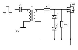
One way to solve this is to isolate the gate drive via an optocoupler or transformer. Using such isolation on the low side floats the Kelvin connection and isolates it from the system 0V (Figure 3). Using a transformer allows the designer to generate the negative off-state gate drive as needed and adjust the turns ratio to scale the positive drive to the optimum value.
Summary
A Kelvin connection to a wired wide bandgap device enables delivery in a TO-247 package that supports high power dissipation. This brings us closer to a switch that is electrically ideal, yet practical for use at high power levels.
Inquiry
If you have any questions regarding this article, please contact us below.
Qorvo manufacturer information top page
If you want to return to Qorvo manufacturer information top page, please click below.
