
![]()
![]() Narrow down by specifying conditions
Narrow down by specifying conditions
現在1888件がヒットしています。check

An optical transceiver module (hereafter referred to as an optical transceiver) performs mutual conversion between electrical and optical signals, and is an essential and important component for optical communication systems. In the unlikely event that a failure occurs in the optical communication system, it will be necessary to check whether there is a problem with the performance of the optical transceiver.
In that case···
・ I don't know how to connect the measuring instrument because the optical transceiver does not have a connector terminal for taking out the electrical signal to the outside.
・ I do not know what to measure for the optical transceiver in the first place
Isn't there a lot of people who get lost? Therefore, in this article, we will solve these questions and introduce the basic knowledge to prepare for failure while touching on the following two points.
(1) Connect the measuring instrument with a coaxial cable using the dedicated evaluation board
(2) Check BER (Bit Error Rate) and signal waveform as typical performance
Types of measuring instruments and measurement contents
First, we will explain the specific equipment and measurement methods required to measure the performance of optical transceivers.
Required boards and equipment
Optical module compliance board
An optical module compliance board (MCB) is a jig board equipped with a coaxial port for exchanging electrical signals from optical transceivers with external devices. There are board products for each form factor, such as for SFP, QSFP, and CFP.
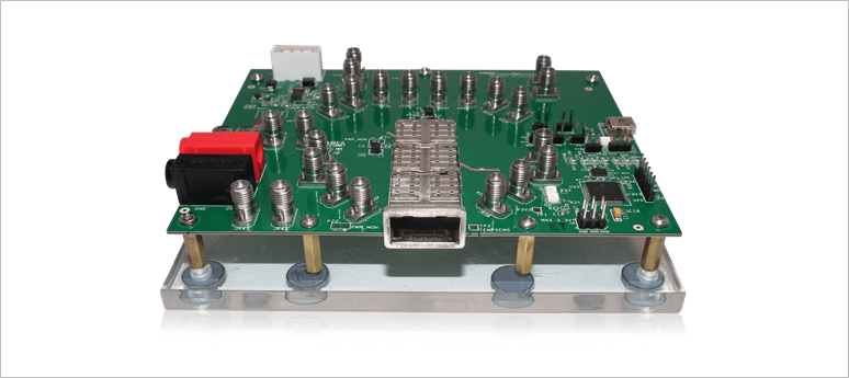
In front of the board is a port for inserting a QSFP28 optical transceiver, and on the other side of the board is a group of coaxial connectors for inputting and outputting electrical signals.
bit error rate tester
A Bit Error Rate Tester (BERT) is a measuring instrument that consists of a pulse pattern generator that sends random bit patterns and an error detector that detects bit errors. The random pattern of 0s or 1s sent by itself is received again, and how much bit corruption occurs during transmission is measured, and the probability of error is expressed in Bit Error Rate (BER). BER is one of the basic performances that allows us to know what percentage of transmission is correct. For example, if 10 12 data are sent and 1 error occurs, it is expressed as Bit Error Rate = 10-12.
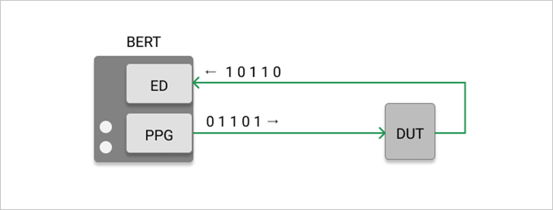
PPG: Pulse Pattern Generator
ED: Error Detector
DUT: Device Under Test
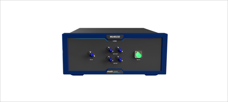
digital sampling oscilloscope
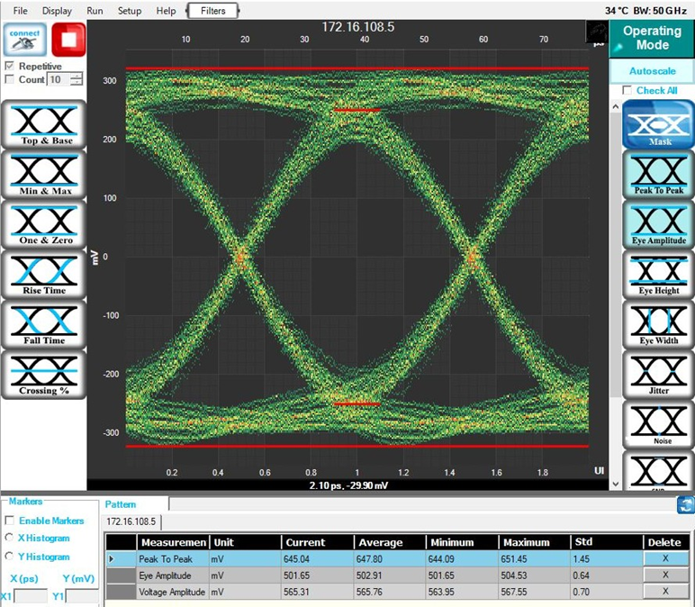
A Digital Sampling Oscilloscope (DSO) is an oscilloscope that displays waveforms of high-speed digital signals. In general, a random pattern consisting of 0s or 1s, called an EYE pattern, is superimposed to observe how clean the waveform is and whether it is not disturbed. The EYE pattern is one of the basic functions that allows you to know how well the waveform is being transmitted.
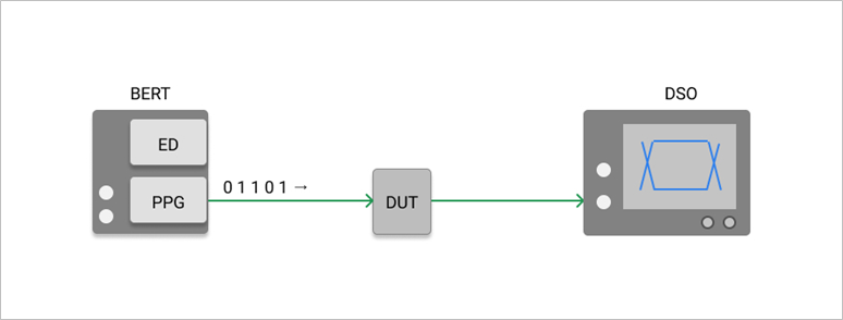
Specifically, the waveform looks like this.
Specific measurement method
Now let's look at specific methods for measuring the bit error rate and eye pattern of optical transceivers.
Optical transceiver bit error rate
The bit error rate of optical transceivers can be measured using BERT and MCB.
There are two ways to handle the optical signal of the optical transceiver.
・ Measuring by looping back as it is
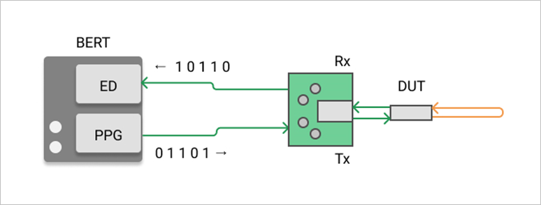
・ Measuring while adjusting the optical power using an optical attenuator
The following measurement methods are explained.
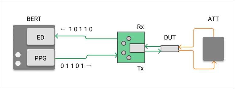
Receiving sensitivity of optical transceiver
If you use an optical attenuator, you can also measure the reception sensitivity of the optical transceiver. An ATT (Attenuator, optical attenuator) can be used to check how the BER changes according to the optical power.
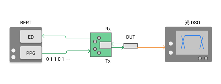
Optical waveform of optical transceiver
Optical waveforms (eye patterns) of optical transceivers can be measured using BERT, MCB, and DSO.
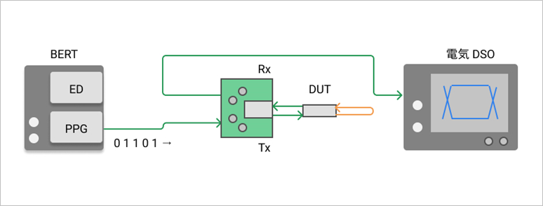
Electrical waveform of optical transceiver
By observing the electrical signal from the MCB, it is also possible to measure the eye pattern of the electrical waveform. (In this case, a DSO for electrical signals is required.)
It is important to prepare the measurement environment in preparation for system failure.
In this article, we introduced the BER and EYE pattern measurement methods for optical transceivers, along with an introduction to measuring instruments.
It is difficult to connect an external measuring instrument with a single optical transceiver, but you can see that it is easy to connect and evaluate using Multilane's boards and measuring instruments.
When constructing an infrastructure network using optical transceivers, it is possible to quickly resolve system failures by preparing these measurement environments.
If you are interested in Multilane's measuring instruments, please feel free to contact us.