- Semiconductor BusinessHOME
- Products and Services of Macnica,Inc.
-
technical information

-
Events and Seminars
- Handling Manufacturer
- Support
- Inquiry
- Click here to purchase products
- Semiconductor business e-mail magazine registration
![]()
![]() Narrow down by specifying conditions
Narrow down by specifying conditions
現在2183件がヒットしています。check

Introduction
The automotive industry is expected to make a rapid transition to electric vehicles in the future in order to combat global warming. Unlike conventional engine vehicles, the large-scale motor drive generates magnetic fields in places around the motor, and it is thought that it will become difficult to use parts that are affected by magnetism, such as the Hall elements that have been used up to now. can be Recently, inductive sensors, which are non-contact and less affected by the surrounding magnetic force, have been attracting attention as well as Hall elements.
Inductive sensors currently used are known to be combined with conductors such as inductive SW. We all know Faraday's Law. It is an electromagnetic induction in which electromotive force is generated in a conductor when a conductor causes a change in the magnetic field and a magnetic field is generated in the conductor that cancels the magnetic field according to the change in the magnetic field.
Principle of Inductive Sensor
See Figure 1. The right side is an image of a transformer, and the left side has an oscillator. According to Faraday's law, even if a direct current is applied to the left side, the generated magnetic field does not change, so no induced electromotive force is generated in the secondary coil, so there is no output.
If alternating current is used, the magnetic field will always change, so an induced electromotive force will act on the secondary coil, and the output will be sent out. If the target in between is moved, the turn ratio of the primary coil and the secondary coil will change, and the voltage of the output waveform will also change. If this outputs a sine wave and a cosine wave, by comparing the voltage values of the output waveforms, you can know where the target is based on each phase of sine and cosine. Although it is an example of a transformer, an inductive sensor measures angles and distances by printing a coil on a board and using this principle.
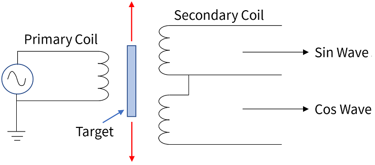
Fig. 1 Inductive Sensor transformer model
As shown in Figure 2, design a primary coil on the board and use this primary coil in an LC resonance circuit with a capacitor. Since it is a resonant circuit, it can generate a magnetic field in the same way as the Primary Coil equipped with an oscillator in Fig. 1. The secondary coil is designed to draw Sin and Cos waveforms. As a result, the primary coil and secondary coil coupling coefficients are dense and sparse, and the voltage value received by the Control IC is received with a voltage value that matches the phases of Sin and Cos. However, the Sin and Cos phase waveforms will not be output in this state, and only the waveform of the Primary Coil due to mutual induction will be output to the Secondary Coil. In order to obtain phase information, it is necessary to disturb the magnetic field generated by the Primary Coil by a conductive Target and convert it into phase information of Sin and Cos waveforms.
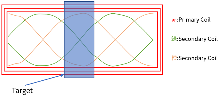
Fig. 2 Inductive Sensor configuration
Fig. 3 shows the Eddy Current from the Coil by Target.
When this eddy current flows to the target, it changes to phase information.
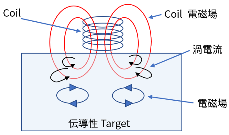
Fig. 3 Coil magnetic field and eddy current
By changing to phase information, the position of the Target can be detected. The formula for calculating the position is
Vp: Primary coil voltage
Ns,Np: Primary Coil, Secondary Coil number of turns
As,Ap: Area where Primary Coil and Secondary Coil are hidden by Target
k(z): Coupling factor of Target and Coil
z: Airgap
By calculating Vsin and Vcos and calculating Arctangent, the position of the Target is calculated. Angle calculation of Rotary Type can be obtained in the same way.
The Inductive Sensor can calculate distances and angles without being affected by dust or water droplets, so it can be used as a non-contact sensor without wear.
Inquiry
If you have any questions regarding this article, please contact us below.
To Microchip manufacturer information Top
If you want to return to Microchip manufacturer information top page, please click below.