- Semiconductor BusinessHOME
- Products and Services of Macnica,Inc.
-
technical information

-
Events and Seminars
- Handling Manufacturer
- Support
- Inquiry
- Click here to purchase products
- Semiconductor business e-mail magazine registration
![]()
![]() Narrow down by specifying conditions
Narrow down by specifying conditions
現在2172件がヒットしています。check

Introduction
This page describes how to create a microcomputer program using the Curiosity High Pin Count Development Board, which is Microchip's 8-bit microcomputer evaluation board. In Microchp's development environment, initialization of peripherals can be easily performed on the GUI using the automatic code generation tool, but here we will create a program with hand code.
usage environment
Evaluation Board
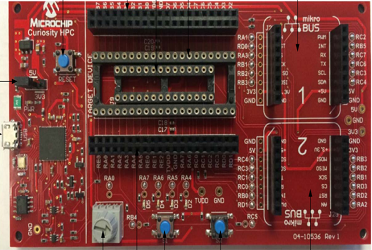
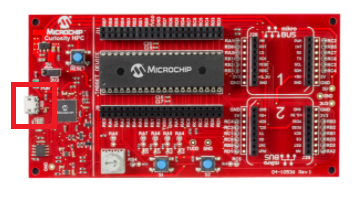
The evaluation board is on the left, using the Curiosity High Pin Count Development Board. (https://www.microchip.com/DevelopmentTools/ProductDetails/PartNO/DM164136)
Microcomputer used
This time, the microcomputer used is the 8-bit microcomputer PIC18F27Q10, and the package is the SPDIP 28-pin type.
I'm using.
Development environment
The development environment uses MPLAB® X IDE and the compiler uses MPLAB® XC8 Compiler.
The versions used this time are MPLAB® X IDE 5.40 and MPLAB® XC8 Compiler 2.20.
MPLAB® X IDE
https://www.microchip.com/mplab/mplab-x-ide
MPLAB® XC8 Compiler
Program overview
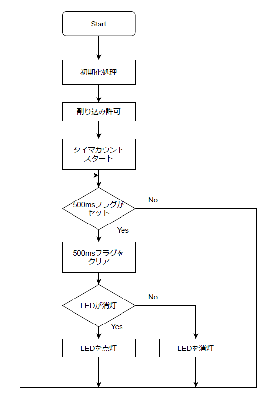
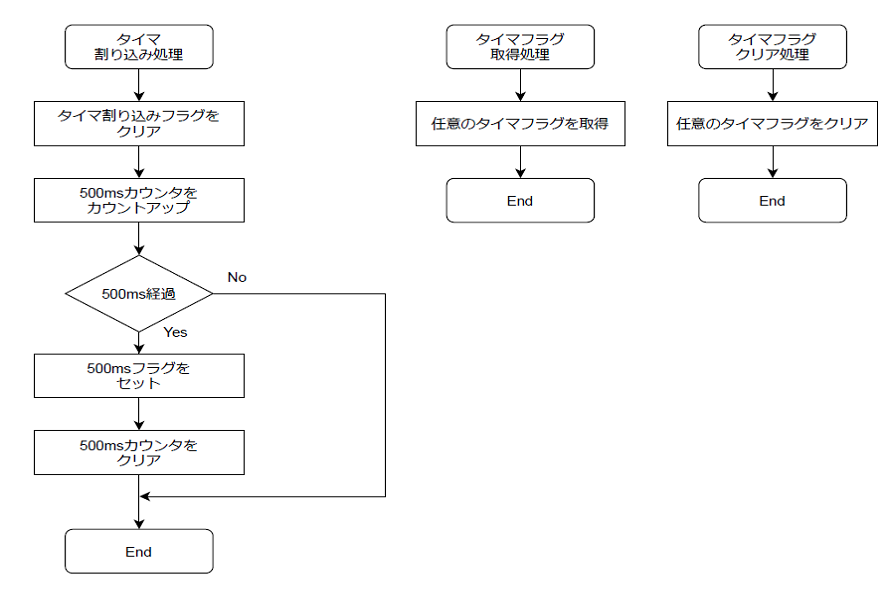
Create a program that blinks the LED mounted on the evaluation board at 500ms intervals using the Timer0 Module of PIC18F27Q10. Timer0 Module can select 8bit or 16bit mode as the count mode, but we will use 16bit mode this time. Use Timer0 to raise an interrupt every 10ms. A 10ms interrupt is used to turn the LED on and off at 500ms intervals.
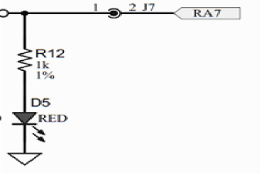
As for the LED on the Curiosity High Pin Count Development Board, port RA7 is connected as shown in the left figure. Setting the port to High turns the LED on, and setting the port to Low turns the LED off.
Create a project
Create a project using MPLAB® X IDE.
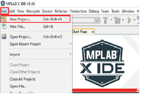
Launch MPLAB® X IDE and click “File” menu → “New Project”.
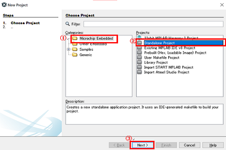
The New Project Box will pop up, so select "Microchip Embedded" → "Standalone Project" → click "Next".
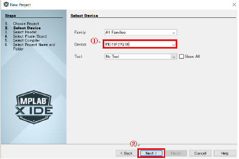
Then select your device. Enter “PIC18F27Q10” which is the microcomputer used this time in the “Device” part and click “Next”.
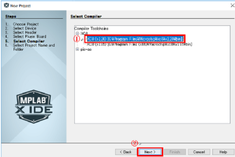
Next, select Compiler. If you have installed MPLAB® XC8 Compiler, "XC8(v2.20)" will be displayed on the screen, so select it and click "Next".
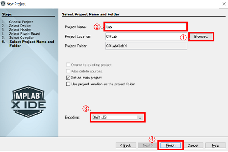
Decide where to save the project and the project name. Click "Browse" in "Project Location" and select an arbitrary project storage location. (Here, a folder called "Lab" is created under the C drive and used as the project storage location.)
Enter the project name in "Project Name". (Here we call it Lab.)
By setting "Encoding" to "Shift JIS", you can use Japanese in comments, etc. Click "Finish" to create the project.
Main project selection
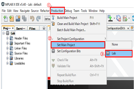
If you have multiple projects on MPLAB® X IDE, you will need to choose which project to work with. To select the project to work on, select the "Production" menu → "Set Main Project" → the project to work on (Lab this time).
If the project was created without any other project on MPLAB® X IDE, the above operation is not necessary.
Configuration Words
PIC microcomputers have Configuration Words. This allows you to set the oscillator to be used when turning on the power of the microcomputer. The PIC18F27Q10 is initially set to use an external oscillator, but the Curiosity High Pin Count Development Board does not have an external oscillator, so the internal oscillator is used.
Therefore, it is necessary to change the Configuration Words. Changing the Configuration Words is easy with MPLAB® X IDE. To change the Configuration Words, select “Productoin” menu → “Set Configuration Bits” → “Configuration Bigts” in MPLAB® X IDE.
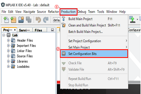
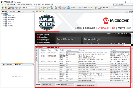
You will see "Configuration Bits" at the bottom of the screen.
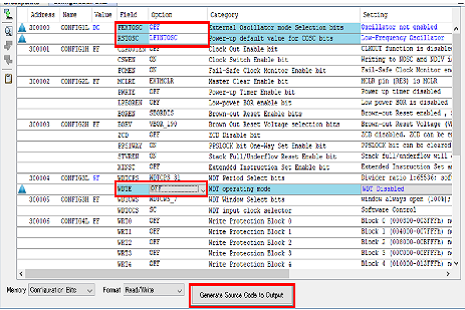
This change changes "FEXTOSC", "RSTOSC", and "WDTE". From the pull-down menu in the "Option" column, set "FEXTOSC" to "OFF", "RSTOSC" to "LFINTOSC", and "WDTE" to "OFF".
With this setting, when the power is turned on, the microcomputer operates with the internal low-speed oscillator and starts operation with the WDT disabled. After completing the above settings, click "Generate Source Code to Output" to display the settings as code.
Copy all the code shown, create a file called "ConfigurationBit.h" and paste the copied code into this file.
create file
The source file and header file created this time are as follows.
·source file
main.c : main program
SystemInit.c: Initialization processing program
timer.c : timer-related program
interrupt.c : Interrupt handling program
・Header file
define.h : declaration of constants etc.
ConfigurationBit.h: Configuration bit setting
SystemInit.h: function declarations used in SystemInit.c
timer.h : function declarations used in timer.c
These files create a new folder called "src" in the created project folder (Lab.x folder) and save them in the "src" folder.
Header files such as register names can be used by writing the following header files, so include them in each source file.
#include <xc.h>Below is a simple representation of what each source file does.
■ main.c file
■SystemInit.c file
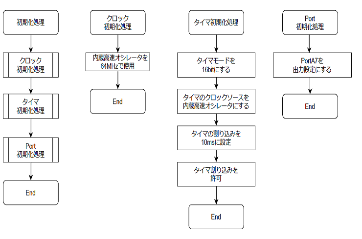
■timer.c file
■interrupt.c file
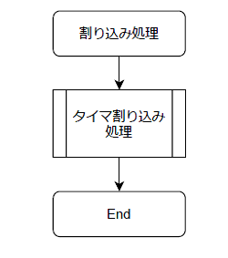
Interrupt handling
By preparing the following function for interrupt processing, processing is passed to this function when a peripheral interrupt occurs. All interrupts come into this function, so check the interrupt flag (PIRx register) and check the corresponding interrupt.
void __interrupt() Interrupt_routine( void ) { }Add source code to project
Now that the program file has been completed, we will add the created source files to the project.
Right-click "Source File" of the project created on MPLAB® X IDE and click "Add Existing Item".
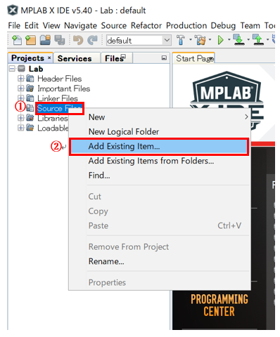
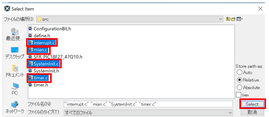
Select the folder with the saved source files, select "interrupt.c", "main.c", "SystemInit.c", "timer.c" and click "Select".
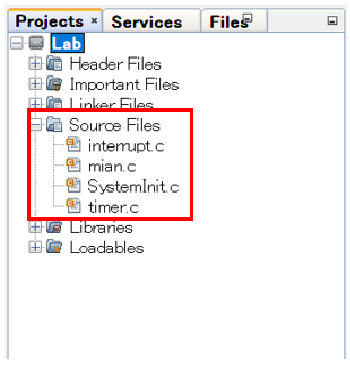
Confirm that the selected source file has been added to "Source Files".
Build source files
Now that the source files have been added, it's time to build.
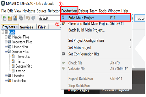
Click “Production” menu → “Build Main Project” to start building.
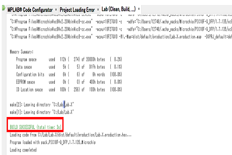
If there are no syntax errors in the C language, "BUILD SUCCESSFUL" is displayed as shown below and the build is completed.
debug
Set the option so that when you start debugging, the operation stops at the first line of the main function. (This setting is saved once, so it is not necessary when debugging from the next time.)
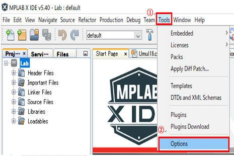
Click Tools menu → Options.
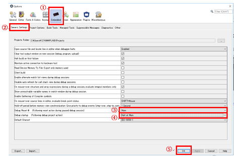
The "Options" Box will appear. On the "Embedded" → "Generic Settings" tab, set "Debug Reset@(Following reset action during paused debug session)" to "Main" and "Debug Startup (Following debug project action) to " Halt at Main” and click “OK”.
Then debug.
First select the debugger. The Curiosity High Pin Count Development Board used this time has an on-board debugger, so you can debug it simply by connecting the PC and the Curiosity High Pin Count Development Board via USB.
Connect the PC and the Curiosity High Pin Count Development Board via USB.
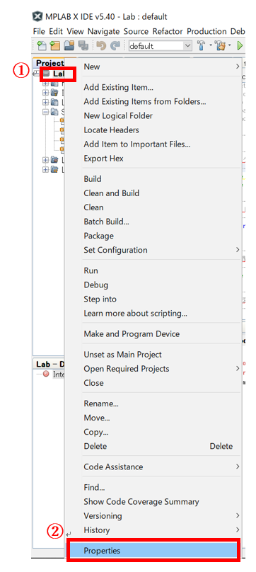
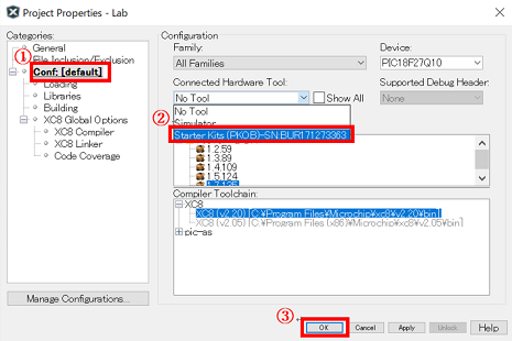
To select the debugger, right-click the project "Lab" created with MPLAB® X IDE and click "Properties" at the bottom.
The "Project Properties" Box will pop up. Select "Conf: [default]" from the "Categories" column, select "Starter Kits (PKOB) - XXX" from the "Connected Hardware Tool" pull-down menu, and click "OK". "Click.
To start debugging, click Debug menu → Debug Main Project.
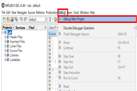
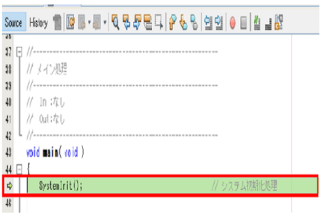
The debug start position will be the first line of the main function and the program will stop.
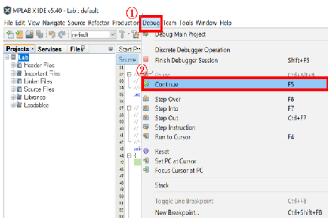
If you click "Debug" menu → "Continue", the program will run and the LED will blink repeatedly at 500ms.
The project used this time can be downloaded from the following.
Notes
We have made every effort to accurately describe the content and downloadable projects on this page, but we do not guarantee the content.
Operations may differ depending on the version of development tools and compilers.
Download the project file here
Inquiry
If you have any questions regarding this article, please contact us below.
Microchip manufacturer information Top
If you want to return to Microchip manufacturer information top page, please click below.