- Semiconductor BusinessHOME
- Products and Services of Macnica,Inc.
-
technical information

-
Events and Seminars
- Handling Manufacturer
- Support
- Inquiry
- Click here to purchase products
- Semiconductor business e-mail magazine registration
![]()
![]() Narrow down by specifying conditions
Narrow down by specifying conditions
現在2189件がヒットしています。check

Introduction
In recent years, as the electronic control of automobiles progresses, the number of ECUs installed in a single automobile is increasing year by year, and there are multiple ECUs for each function. Connected via Ethernet.
Among them, CAN is one of the most widely adopted in-vehicle communication networks.
In addition, as the amount of data exchanged between ECUs is increasing, the adoption of CAN-FD, which has a higher data bandwidth than CAN, is increasing.
On this page, we will explain the issues and solutions of controller ICs, which are indispensable for CAN communication, which is most commonly used in in-vehicle communication networks, and CAN-FD communication, which is expected to be widely adopted in the future, along with trends. I will continue.
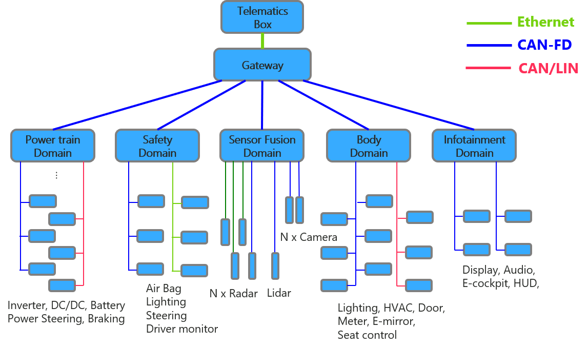
The ECUs installed in a single vehicle are arranged according to their respective functions, and are connected by CAN/LIN/CAN-FD/Ethernet respectively, and the number of such communication networks is also increasing.
【table of contents】
1. What configuration is required to achieve CAN communication?
2. ECU integration trends and concerns
3. Solved with FPGA? What is CAN controller by FPGA?
4. Would you like to actually try CAN communication with FPGA?
What configuration is required to achieve CAN communication?
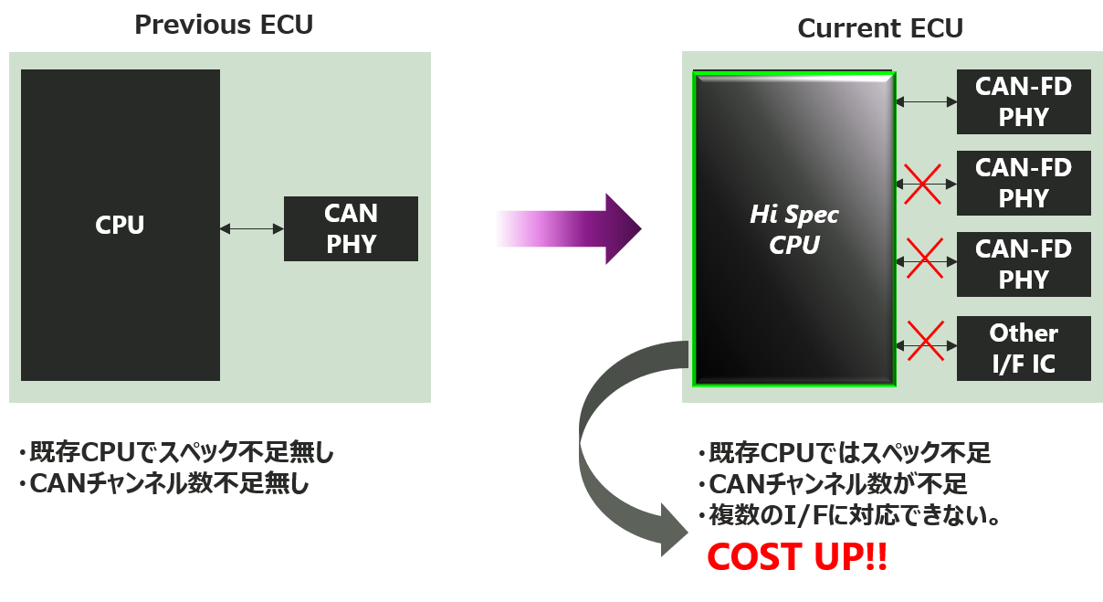
When implementing CAN communication, the most common configuration is to implement the CAN controller function in a microcomputer and use an external CAN transceiver to achieve CAN communication, as shown in the lower left figure. increase. However, it is known that there are some issues with this configuration depending on the case. It is the lack of specifications due to the lack of channels (lack of I/O) on the microcomputer side when the number of CAN/CAN-FD channels increases and the amount of processing increases.
Will that actually happen?
We will introduce the following items based on technological trends and actual examples in the automobile industry.
ECU Integration Trends and Concerns
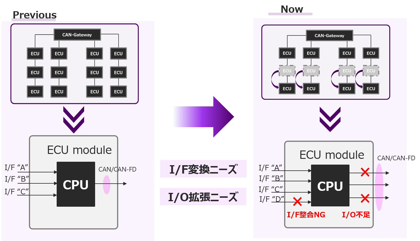
As mentioned at the beginning, the number of ECUs installed in recent automobiles has been increasing year by year, and the number of ECUs installed in one automobile has become enormous. An increase in the number of ECUs raises concerns about an increase in the number of harnesses connecting ECUs and an increase in the weight of the entire vehicle due to an increase in the number of parts that make up the ECU module.
In particular, the weight occupied by harnesses is an important factor that affects the fuel efficiency of automobiles and the cruising range of electric vehicles. There is a movement toward "ECU integration" to reduce the number of harnesses that connect between them.
Due to the trend toward ECU integration, the functions handled by a single ECU are consolidated, so the number of communication lines connected to a single ECU and the types of interfaces increase, so it is used as a CAN/CAN-FD controller IC. There are cases where there are concerns about lack of specs due to insufficient number of channels (lack of I/O) in the microcomputer inside the ECU and an increase in the amount of processing.
Solved with FPGA? What is CAN controller by FPGA?
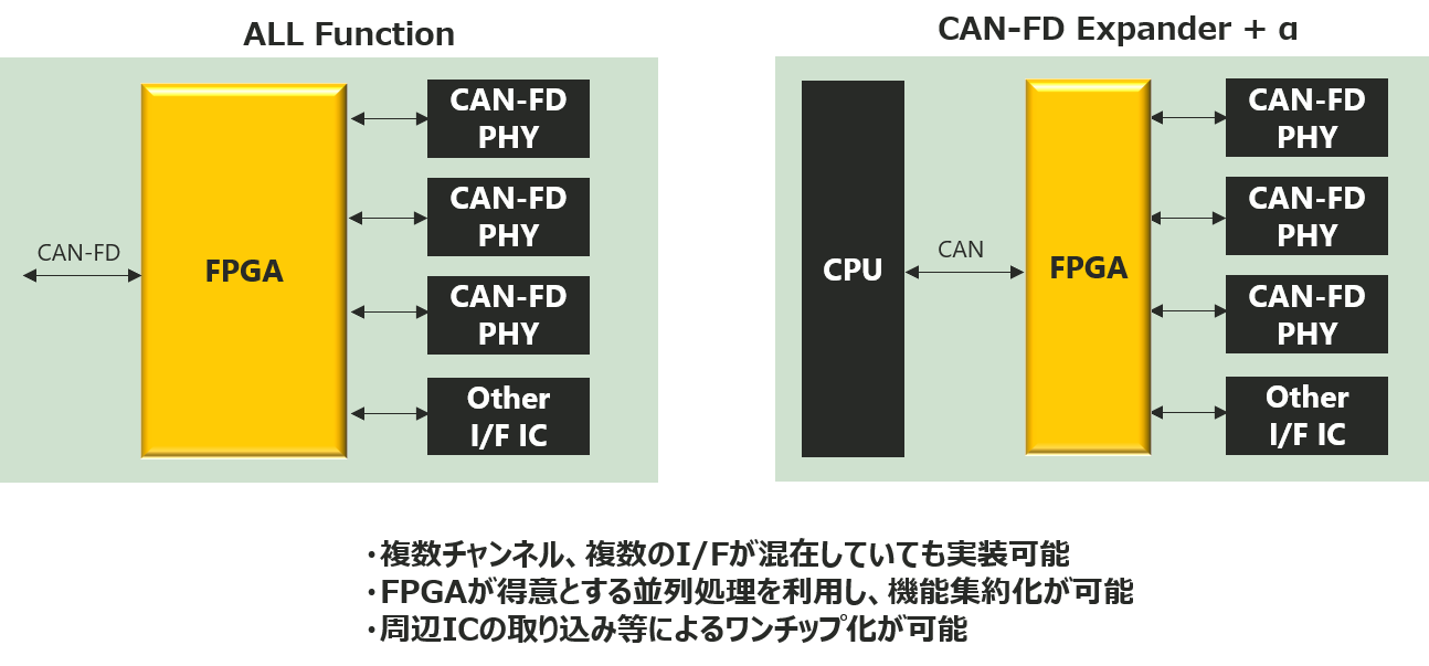
As a solution to the insufficient number of channels (lack of I/O) and lack of specifications in the microcomputer inside the ECU used as the CAN/CAN-FD controller IC, there is a method of using FPGA as the controller IC. Compared to microcontrollers, FPGAs offer greater flexibility, a greater number of I/Os that can be freely used by the user, and low latency due to parallel processing unique to hardware processing. It is also a device that can solve problems.
By using FPGA as a controller IC, as shown in the lower left figure, it is possible to flexibly and programmatically correspond to the increased number of CAN/CAN-FD channels and different I/F types. is. The lower left figure is a configuration that assumes that all the functions of the microcomputer are replaced with FPGA, but the lower right figure is a configuration that aims to reduce the total cost and expand flexibility by combining an inexpensive microcomputer and a small FPGA. increase.
Would you like to actually try CAN communication with FPGA?
I hope you have understood that a CAN controller can also be realized with an FPGA. However, there are many things that the article cannot cover. In fact, we have prepared a demo environment that consists of a Lattice FPGA that implements a CAST IP and an Infineon transceiver.
The video introduces the advantages of implementing with FPGA in an easy-to-understand manner, and the second half also introduces an overview of the demo environment.
■Overview of the video
・CAN-FD needs due to ECU integration
・Advantages of realizing a CAN controller with FPGA
・About CAST's IP
・Demonstration configuration and usage
・Introduction of GUI during demonstration
・Demo use case
It's a free seminar video that you can learn in 10 minutes, so please take a look at it below.
