
![]()
![]() Narrow down by specifying conditions
Narrow down by specifying conditions
現在1888件がヒットしています。check

Features of Switching Mode
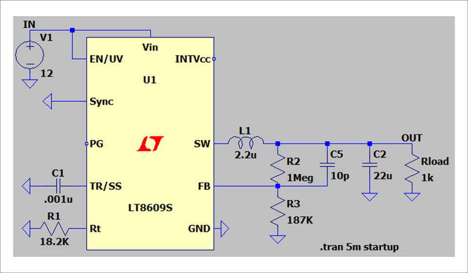
ADI non-isolated DC/DC With converter products, it is possible to set the mode in which switching is performed according to the operating conditions of the load (this cannot be changed for some products). Therefore, it operates in the optimum switching mode according to the customer's application and load driving conditions.
The following three methods are introduced here.
・Forced continuous mode
・Pulse skip mode
・Burst mode
Basically, the difference between each mode occurs when the load current is much smaller compared to the steady state.
The outline of the image waveform and its advantages and disadvantages are explained below.
forced continuous mode
It does not depend on the load current and outputs switching pulses even when the inductor current is in the negative region.
·merit
→ It switches at a constant cycle without depending on the inductor current.
The load response characteristics are the fastest among each mode.
·Demerit
→ Efficiency at light load is worse than other modes
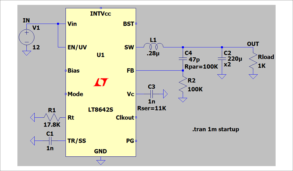
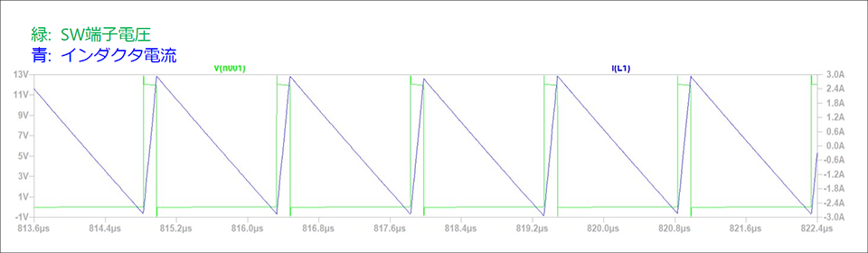
Pulse skip mode
If the inductor current is excessive at light load, the switching operation is turned off (skipping pulses) at regular intervals.
·merit
→ Efficiency at light load is better than forced continuous mode.
Load response characteristics are better than in burst mode.
·Demerit
→ Not No. 1 in terms of efficiency and response characteristics at light loads.
A region occurs where the switching frequency is not constant.
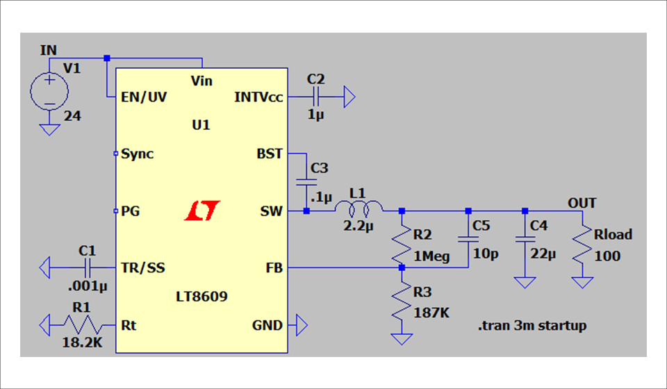
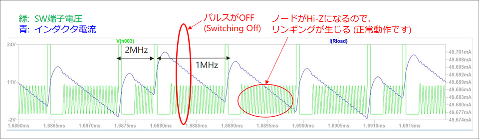
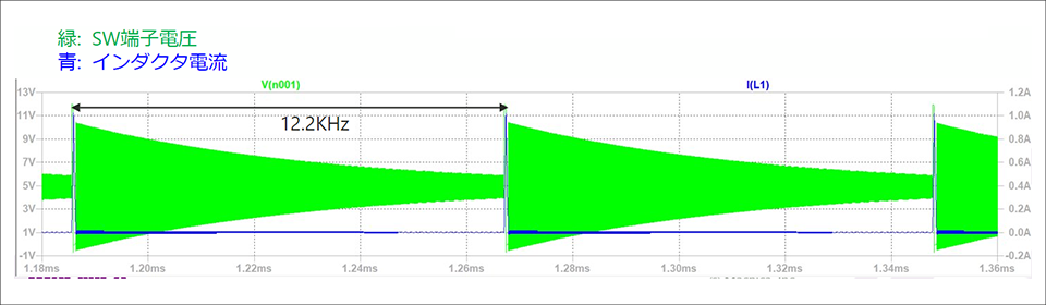
burst mode
At light loads, the output voltage is maintained only by the capacity of the output capacitor. Repeated operation of turning on the switch when the output voltage falls below a certain threshold. The inside of the IC is also SLEEP except where necessary.
·merit
→ Efficiency is best at light load.
·Demerit
→Response characteristics worsen (explanation required)
Vout_ripple is the highest among the three modes (≤10mVp-p)
|
Performance |
forced continuous Forced continuous mode |
light load Pulse Skip mode |
light load Burst mode |
|
Current consumption at light load |
X |
〇 A few mA for the LT8609S |
◎ 2.5uA for LT8609S |
|
Load response |
◎ |
〇 |
△ |
|
frequency drop |
do not do |
Fsw drops by 1/N as load current decreases |
Fsw decreases linearly as load current decreases |
|
frequency drop threshold |
none |
low About 60mA for LT8609S @12Vin, 3.3Vout, 2.2uH 2MHz. |
high About 400mA for LT8609S @12Vin, 3.3Vout, 2.2uH 2MHz. |
In particular, in automotive applications that have requirements such as CISPR 25, there is a possibility that the spectrum will stand out in the frequency band where the frequency drop occurs, rather than the "magnitude" from the noise perspective. Since pulse-skipping and burst modes change the frequency as explained above, there is a possibility that the spectrum in that band can be seen.
Whether or not there is a problem will be judged by the customer based on the results of actual machine measurement.
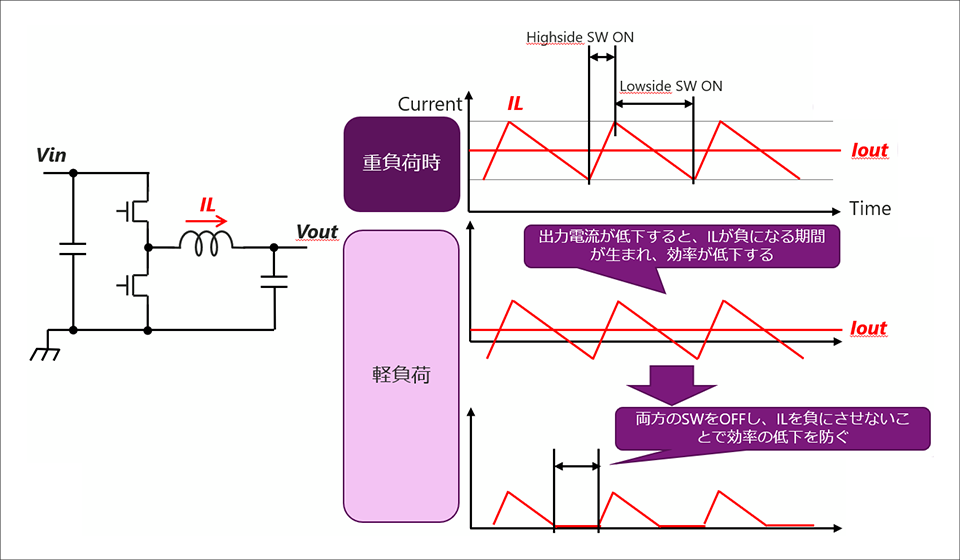
The mechanism that causes the efficiency to drop when the load changes to light load while operating under heavy load is as follows.
Inquiry
In this article, we introduced each feature of the switching mode. For more information, please contact us below.
Analog Devices Manufacturer Information Top
If you want to return to Analog Devices Manufacturer Information Top, please click the button below.