- Semiconductor BusinessHOME
- Products and Services of Macnica,Inc.
-
technical information

-
Events and Seminars
- Handling Manufacturer
- Support
- Inquiry
- Click here to purchase products
- Semiconductor business e-mail magazine registration
![]()
![]() Narrow down by specifying conditions
Narrow down by specifying conditions
現在2183件がヒットしています。check

I think that an I2C bus is used to connect multiple devices on an FPGA board for memory or power sequence management. In some systems, an I2C bus is also used between boards.
The I2C bus is a simple two-wire system!
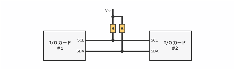
The I2C bus requires only two single clock (SCL) and single data (SDA) lines to communicate between devices.
Because it is a simple method, it is often used in SMBus, PMBus, ATCA IPMB buses, and other buses used in communication equipment.
Simple but watch out for trouble!
People tend to think that the I2C bus is easy to design with because it is a simple two-wire, low-speed communication system.
However, there are many cases where communication does not work well.
The possibility of problems is particularly high when a connection to a backplane is required for communication equipment, or when communication is carried out via long wiring between IO cards.
What caused the communication error?
The communication error is most likely caused by the wiring capacitance exceeding the I2C bus specifications, which state that the maximum wiring capacitance is 400pF.
When connecting to a backplane or using long wiring between IO cards, the wiring capacitance may exceed the I2C standard, causing the rising waveform to become distorted and resulting in communication errors, as shown in Figure 1.
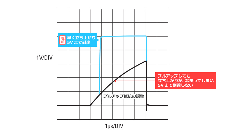
Is it possible to fix it by adjusting the pull-up resistor?
Normally, if the rising waveform is dull, the countermeasure is to increase the pull-up current (reduce the pull-up resistance) so that it can be driven even if the wiring capacitance is large.
However, care must be taken when making the pull-up current too large, as a side effect, the low level will rise (pull-up current x parasitic resistance), which may result in the VOL specification being exceeded.
So, if communication errors cannot be avoided by adjusting the pull-up resistor, what should be done to resolve the issue?
Solutions to improve communication errors
What should you do if you need to connect to a backplane, such as in a communications device, or if you cannot avoid communication errors due to parasitic capacitance when connecting boards with a flat cable for I2C bus communication?
A workaround for non-compliant parasitic capacitance is to use Analog Devices' IC bus buffer products.
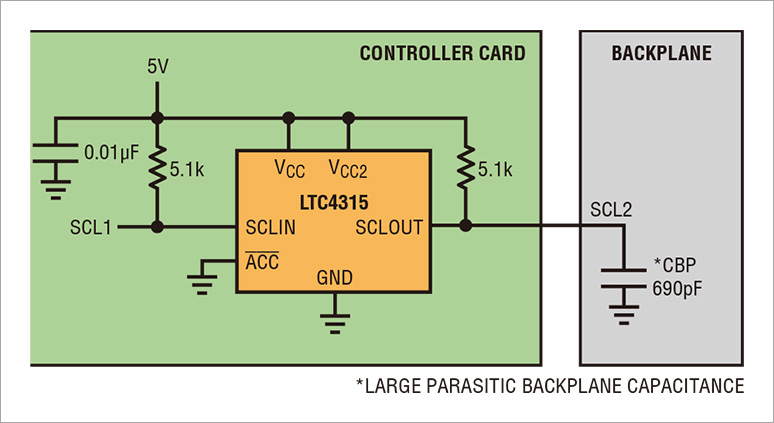
The LTC4315 has a Rise Time Accelerator function that can improve a dull rising waveform.
As shown in Figure 3, by placing the LTC4315 on the controller board, it is possible to communicate normally even when connected to a backplane.
The LTC4315 is an essential product for IC bus communication, solving the problem of large parasitic capacitance between boards (devices).
Click here to purchase products
Inquiry
If you have any questions regarding this article, please contact us below.
Analog Devices Manufacturer Information Top
If you want to go back to Analog Devices Manufacturer Information Top, please click below.