- Semiconductor BusinessHOME
- Products and Services of Macnica,Inc.
-
technical information

-
Events and Seminars
- Handling Manufacturer
- Support
- Inquiry
- Click here to purchase products
- Semiconductor business e-mail magazine registration
![]()
![]() Narrow down by specifying conditions
Narrow down by specifying conditions
現在2183件がヒットしています。check

Diverse Analog Sensors in the IoT Era
Various sensors are used in products around us. In recent years, even in the fields of IoT that have been attracting attention, we can see that sensors are used for a variety of purposes.
Sensor usage examples
Factory: Collect and analyze information from vibration sensors attached to machine tools. Use for remote monitoring and predictive maintenance.
Agriculture: Collect and analyze information on temperature, humidity, soil moisture, etc. to adjust watering frequency, fertilizer timing, etc.
Healthcare: Collecting physical information such as heart rate to determine health status

It would be easy if the sensor outputs were uniform, but of course they are not.
Module types have digital output, and even analog sensors generally have different output methods, such as different amplitudes, differential/single output, and different output impedance.
The terminal device that collects sensor information has an analog input to obtain the sensor information, but how should this part be designed? Of course, it's easy if the sensor is decided. All you have to do is create it to match that sensor.
However, there are certainly terminal devices that are expected to be connected to a wide variety of sensors. What should we do in such cases?
Analog circuit design concepts that take into account various analog inputs
First, consider analog sensor inputs with different amplitudes.
Basically, you will be adjusting the amplifier circuit of an op amp, which is the most basic of op amps.
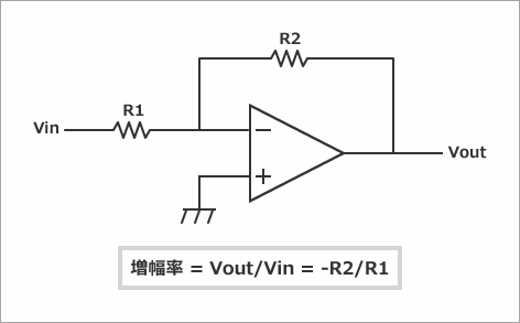
In other words, the amplification factor is determined by the ratio of R1 and R2 above, so by adjusting these resistors it is possible to accommodate inputs of various amplitudes.
Being able to change the resistance via software makes things easier during mass production, so I think it would be better to use a digital potentiometer.
Analog Devices offers a wide variety of digital potentiometers for you to choose from.
Analog Devices Digital Potentiometer Product Page
Another option would be to line up resistors and use an analog switch to select the resistor to be used.
In any case, the fact is that you must consider many things, such as selecting the resistance value, taking into account resistance variations, and layout. Even though it is a simple circuit, there are still many things to consider.
Here I would like to show you an easier way.
アナログ・デバイセズ社 Circuits from the Lab の活用
Analog Devices provides a reference circuit called CFTL (Circuits from the Lab).
To put it simply, CFTL is a collection of reference circuits for achieving certain functions, and these circuits are not only provided on a desk but are also provided as evaluation boards, along with their circuit diagrams, layout information, and even experimental data. Users can use all or part of a circuit that has a proven track record of operation as is.
Circuits from the Lab Reference Designs
Reference design ideal for analog sensor inputs with different amplitudes
今回の用途ではCN0385というCFTLが使えそうです。
ブロック図としては以下のようになっています。
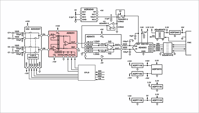
信号ラインの構成を簡単に説明します。
- ADG5027: 8-channel differential multiplexer
- AD8251: Instrumentation amplifier with PGA
- AD8475: Single-input to differential-output ADC driver
- AD4003: 18-bit, 2.0 MSPS SAR type AD converter
- ADuM141E: Digital isolator for isolating digital signals
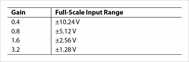
In particular, the AD8251 has a PGA (Programmable Gain Amp) and can handle analog inputs of various amplitudes. Specifically, it can handle the following general input ranges:
What do you think?
Using the CN0385 solves the amplitude problem and even adds an AD converter and isolation.
Of course, if you don't need such a high-precision AD converter, you can replace it, and if you don't need isolation, you don't have to use that part.
We believe that using the proven CFTL will make a significant contribution to shortening the design period.
Learn more about CN0385
Purchase CN0385 here
その他の多様なアナログ入力に対しては
Assuming we've managed to overcome the amplitude issue, there are a variety of other analog sensor outputs. We'll explain how to think about each one.
- Analog sensor output with high output impedance
This refers to the output of a photodiode or a sensor with a warning such as "Use a shielded cable that is not affected by noise." In this case, it is essential to use a "low bias" amplifier in the first stage.
It is advisable to place a low-bias op amp such as the ADA4610 in the first stage.
- Thermocouples
This is a bit tricky. There is the issue of what to do about the zero-point guarantee circuit. Of course, it is possible to make it specifically for thermocouples, but it would be better to make it general-purpose if possible. Analog Devices provides amplifiers specifically for thermocouples, and the AD8494/95/96/97 can be used depending on the type of thermocouple.
- 微小電圧入力
ロードセル入力などは非常に微小な振幅となります。ゲインとしては100倍以上かけないといけない場合もありますので、上記紹介したCN0385でも対応できない範囲です。高ゲインの場合はオフセットにもゲインがかかるため「低オフセット」というのがキーワードとなります。
ADA4638など、チョッパータイプでオフセットをキャンセルできるタイプのアンプがお勧めです。
- 電流入力
電流入力は抵抗などで電圧に変換して入力することが一般的かと思います。
- ICP Sensor
A current source and AC coupling circuit are required.
As mentioned above, the amplifier that can be used varies depending on the application, so it is currently difficult to support various analog inputs using software configuration alone.
It may be a good idea to use a general-purpose package (such as SOIC8 pin) so that you can respond by simply replacing the IC. (For example, prepare a pattern for SOIC8 pin in front of CN0385 and select the IC according to the sensor.)
Using CFTL to make circuit design easier
It is quite difficult to create a universal product that can connect to all analog sensors, but Analog Devices believes that it has covered most of the needs with its CFTL reference circuits and diverse analog product lineup.
Click here for recommended articles/materials
Click here to purchase products
Inquiry
If you have any questions regarding this article, please contact us below.
Analog Devices Manufacturer Information Top
If you want to go back to Analog Devices Manufacturer Information Top, please click below.